KENR6932 11
Disassembly and Assembly Section
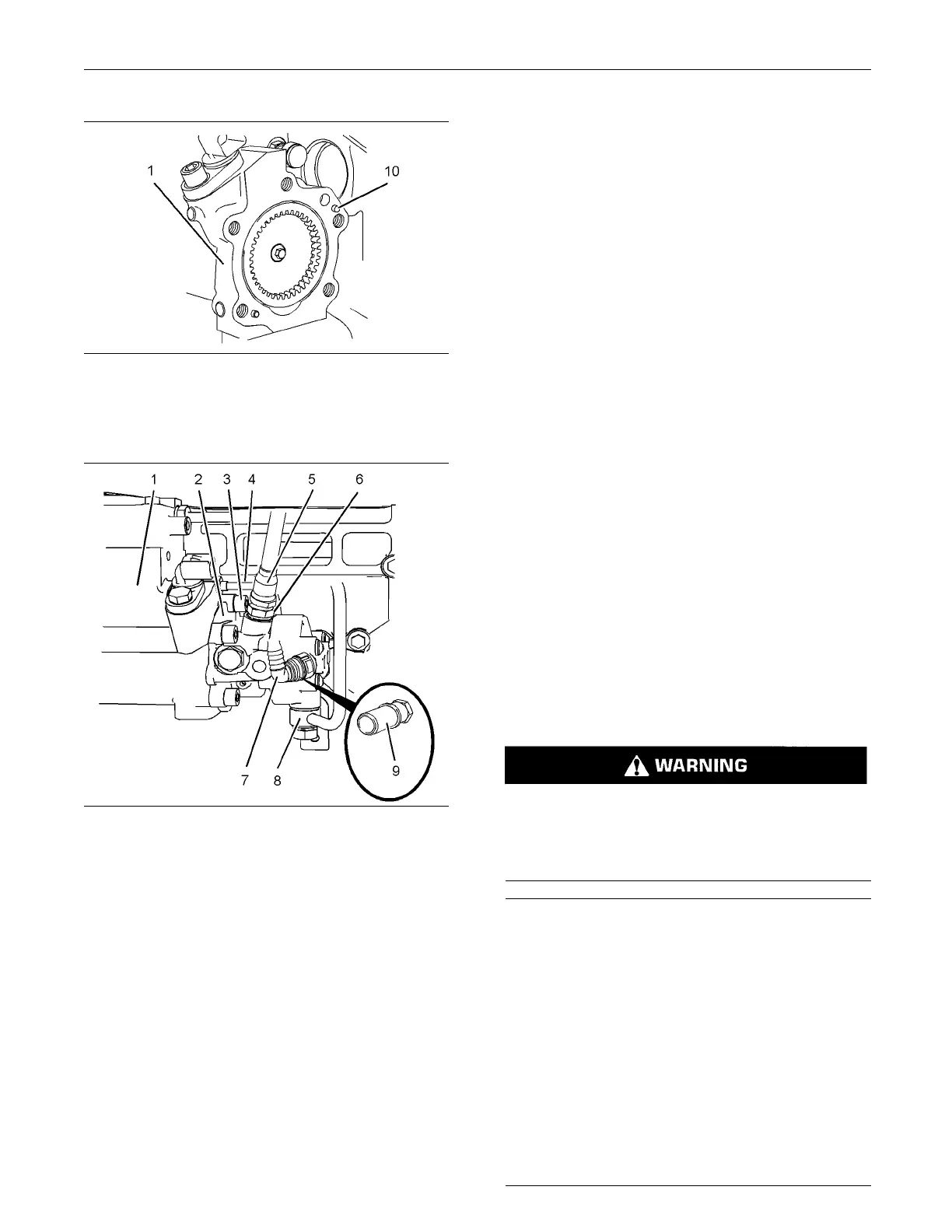
g01335043
Illustration 11
3. Align the holes in fuel transfer pump (2) with
dowels (10) in fuel injection pump (1). Install the
fuel transfer pump to the fuel injection pump.
g01334899
Illustration 12
4. Use an allen wrench with a ball end to install the
allen head screws (3). Tighten the allen head
screws to a torque of 30 N·m (22 lb ft).
5. Remove the plugs and the caps from the ports
and tube assemblies.
6. Install tube assembly (4) for the engine oil supply
to fuel injection pump (1). Install new washers to
the banjo bolt for oil supply tube assembly. Install
the banjo bolt to the cylinder block. Tighten both
connectors to a torque of 15 N·m (11 lb ft).
7. Install tube assembly (8) for the fuel return to fuel
transfer pump (2) and to the cylinder head. Tighten
both banjo bolts to a torque of 21 N·m (15 lb ft).
8. Install a new O-ring seal to connector (6). Install
connector (6) to fuel transfer pump (2). Tighten
theconnectortotorqueof15N·m(11lbft).
9. If necessary, install a new O-ring seal to connector
(9) and install
connector (9) to fuel transfer pump
(2). Tighten the connector to torque of 15 N·m
(11 lb ft).
10. Connect plastic tube assembly (5) to the outlet of
fuel transfer pump (2).
11. Install plastic tube assembly (7) to fuel transfer
pump (2).
12. Restore the fuel supply.
13. Remove the ai
r from the fuel system. Refer to
System Operation, Testing and Adjusting, “Fuel
System - P rime”.
i02654510
Fuel M anifold ( Rail) - Remove
and Install
Removal Procedure
Start By:
a. Remove the fuel injection lines. Refer to
Disassembly and Assembly, “Fuel Injection Lines
- Remove”.
b. If necessary, remove the fuel pressure sensor.
Refer to Disassembly and Assembly, “Fuel
Pressure Sensor - Remove and Install”.
Contact with high pressure fuel may cause fluid
penetration and burn hazards. High pressure fu-
el spray may cause a fire hazard. Failure to fol-
low these inspection, maintenance and service in-
structions may cause personal injury or death.
NOTICE
Ensure that all adjustments and repairs that are
carried out to the fuel system are performed by
authoris
ed personnel that have the correct train-
ing.
Before be
gining ANY work on the fuel system, re-
fer to Operation and Maintenance Manual, “Gen-
eral Hazard Information and High Pressure Fuel
Lines” fo
r safety information.
Refer to System Operation, Testing and Adjusting,
“Cleanli
ness of Fuel S ystem Components” for de-
tailed information on the sta ndards of cleanliness
that must be observed during ALL work on the fu-
el syste
m.

 Loading...


