KENR6932 71
Disassembly and Assembly Section
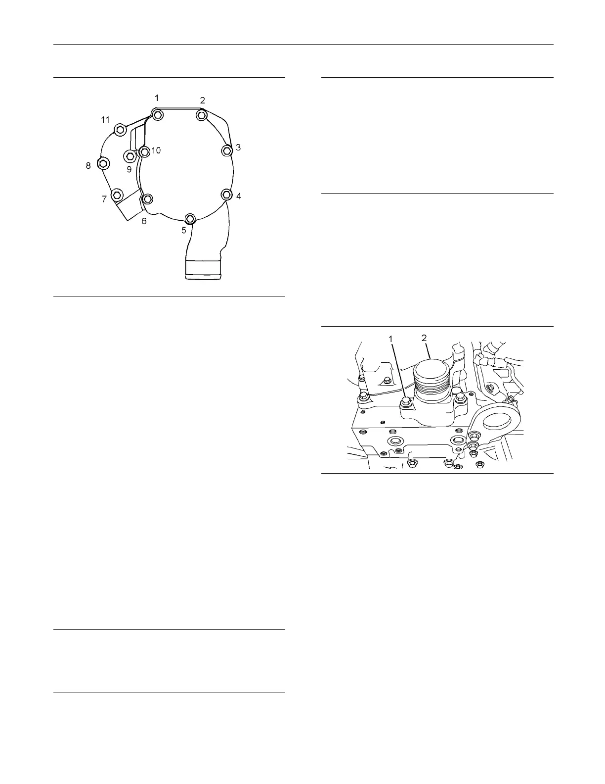
g01336661
Illustration 122
9. Tighten bolts (4) and (7) in the sequence that is
shown in Illustration 122 to a torque of 22 N·m
(16 lb ft).
10. Install the hose to the water pump inlet. Tighten
the hose clamps.
11. Fill the cooling system with coolant. Refer to
Operation and Maintenance Manual, “Cooling
System Coolant - Change” for the correct
procedure.
End By:
a. Install the fan and the fan pulley. Refer to
Disassembly and Assembly, “Fan - Remove and
Install”.
i02654555
Water Temperature Regulator -
Remove and Install
Removal Procedure
NOTICE
Keep all parts clean from contaminants.
Contaminants may cause rapid wear and shortened
component life.
NOTICE
Care must be taken to ensure that fluids are contained
during perform
ance of inspection, maintenance, test-
ing, adjusting and repair of the product. Be prepared to
collect the fluid with suitable containers before open-
ing any compar
tment or disassembling any compo-
nent containing fluids.
Dispose of all
fluids according to local regulations and
mandates.
1. Drain the coolant from the cooling system to a
level below th
e water temperature regulator, into
a suitable container for storage or for disposal.
Refer to Operation and Maintenance Manual,
“Cooling Sys
tem Coolant - Change” for the correct
draining procedure.
2. Loosen the ho
se clamps from the upper radiator
hose and disconnect the upper radiator hose from
water temperature regulator housing (2).
g01336665
Illustration 123
Typical example
3. Remove bolts (1) from water temperature
regulator housing (2).
4. Remove water temperature regulator housing (2)
from the cylinder head.
Note: Note the orientation of the water temperature
regulator housing.

 Loading...


