114 KENR6932
Disassembly a nd Assembly Section
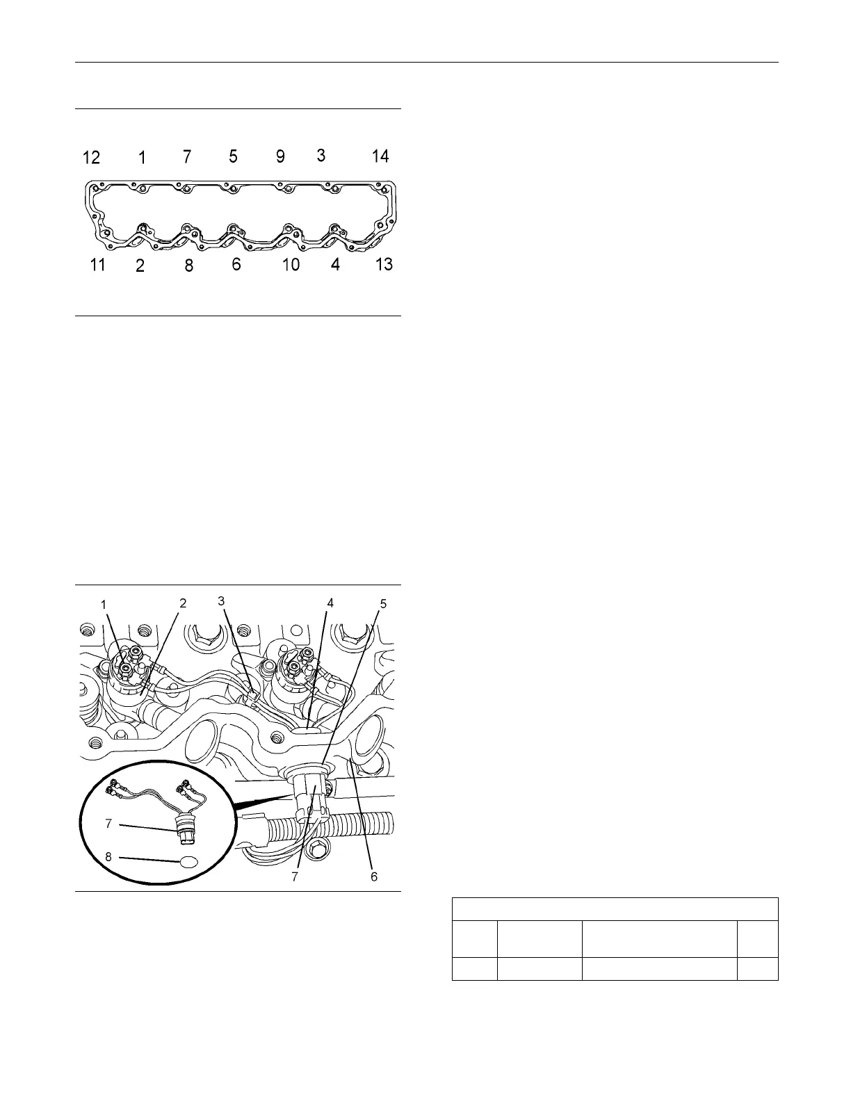
g01354235
Illustration 222
Tightening sequence for the valve mechanism cover base
3. Position valve mechanism cover base (6) on the
cylinder head. Temporarily install two long bolts
from the valve mechanism cover in positions (X).
Note: The long bolts must be installed in order to
align the valve mechanism cover base.
4. Gradually tighten the captive bolts that secure
the valve mechanism cover base to a torque of
9 N·m (79 lb in) in the sequence that is shown in
Illustration 222.
5. Remove the bolts from positions (X).
g01355167
Illustration 223
Typical exam p le
6. If necessary, install the harness assemblies for the
electronic unit injectors. Follow Steps 6.a through
6.e in order to install the harness assemblies to
the electronic unit injectors.
a. Ensure that harness assembly (4) and the bore
in valve mechan
ism cover base (6) are clean
and free from damage. Replace any damaged
components.
b. Use Tooling (B) to lubricate a new O-ring
seal (8). Install O-ring seal (8) onto harness
assembly (4)
.
c. From the inside of valve mechanism cover
base (6), pus
h harness assembly (4) into the
valve mechanism cover base.
d. Use Tooling (
A) to install circlip (5).
e. Repeat Steps 6.a through 8 for the remaining
harness asse
mbly.
7. Use a deep socket to connect harness (4) to
electronic u
nit injectors (2). Use Tooling (C) to
tighten connectors (1) to a torque of 2.4 N·m
(21 lb in).
8. If necessary, install new cable straps (3) to
harness assemblies (4).
Note: Ensure that cable straps are to OE
specification.
9. Connect plugs (7) to harness assemblies (4).
End By:
a. Install new fuel injection lines. Refer to
Disassembl
y and Assembly, “Fuel Injection Lines
-Install”.
b. Install th
e valve mechanism cover. Refer to
Disassembly and Assembly, “Valve Mechanism
Cover - Remove and Install”.
i02654548
Valve Mech an ism Cover Base -
Remove and
Install
Removal Procedure
Table 52
Required T
ools
Tool
Part
Number
Part Descr
iption
Qty
A
-
Circlip Pliers 1

 Loading...


