KENR6932 73
Disassembly and Assembly Section
NOTICE
Keep all parts clean from contaminants.
Contaminants may cause rapid wear and shortened
component life.
g01336668
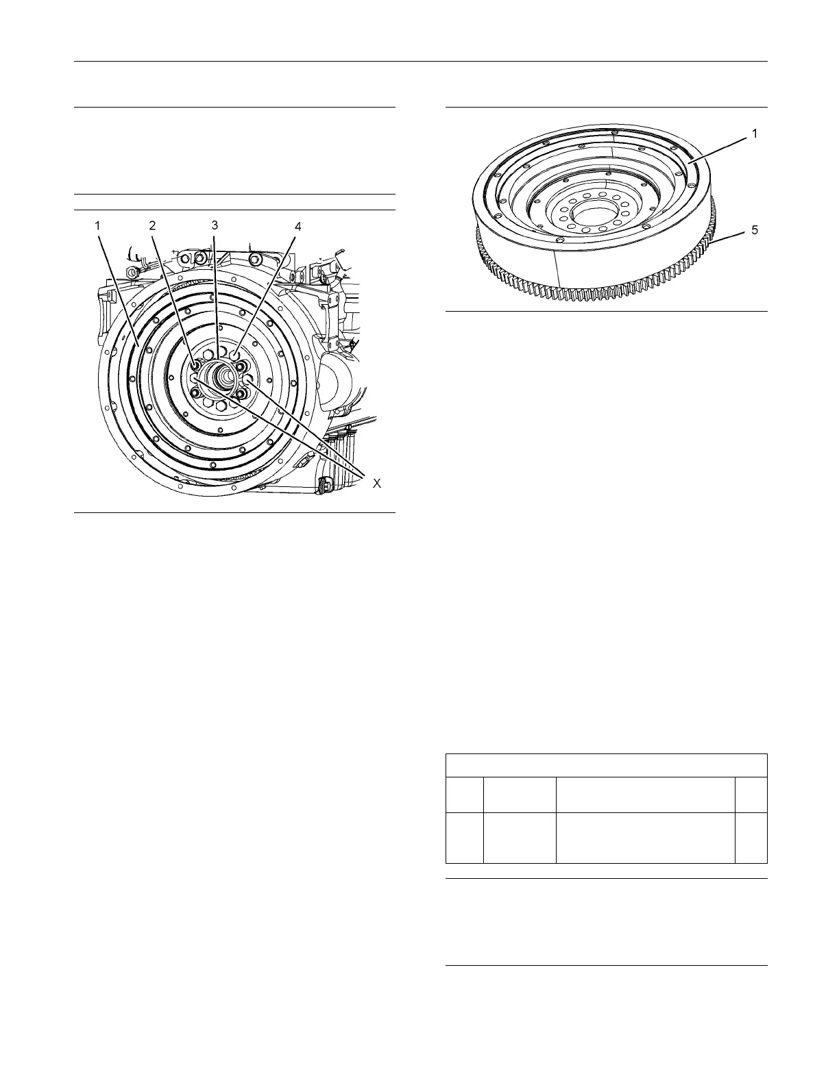
Illustration 127
Typical exam p le
1. Remove bolts from position (X) on flywheel (1).
2. Install Tooling (A) in position (X) on flywheel (1).
3. Attach a suitable lifting device to flywheel (1).
Support the weight of the flywheel. The flywheel
can weigh 70.6 kg (155 lb).
4. If necessary, remove bolts (2) that secure the
housing for pilot bearing (3) to flywheel (1).
Remove the housing for pilot bearing (3).
5. Remove remaining bolts (4).
6. Use the lifting device to remove the flywheel from
the engine.
g01336669
Illustration 128
Typical example
7. Inspect flywheel (1) and ring gear (5) for wear
or damage. Replace any worn components or
damaged components.
8. To r e mo v e flywheel ring gear (5), follow steps 8.a
and 8.b.
a. Place the flywheel assembly on a suitable
support.
b. Use a hammer and a punch in order to remove
ring gear (5) from flywheel (1).
Note: Identify the orientation of the teeth on the
flywheel ring gear.
i02654492
Flywheel - Ins tall
Installat
ion Procedure
Table 24
Required Tools
Tool
Part
Number Part Description Qty
A
-
Guide Stud
(1/2 inch - 20 UNF by 4
inch)
2
NOTICE
Keep all parts clean from contaminants.
Contaminants may cause rapid wear and shortened
component life.

 Loading...


