92 KENR6932
Disassembly a nd Assembly Section
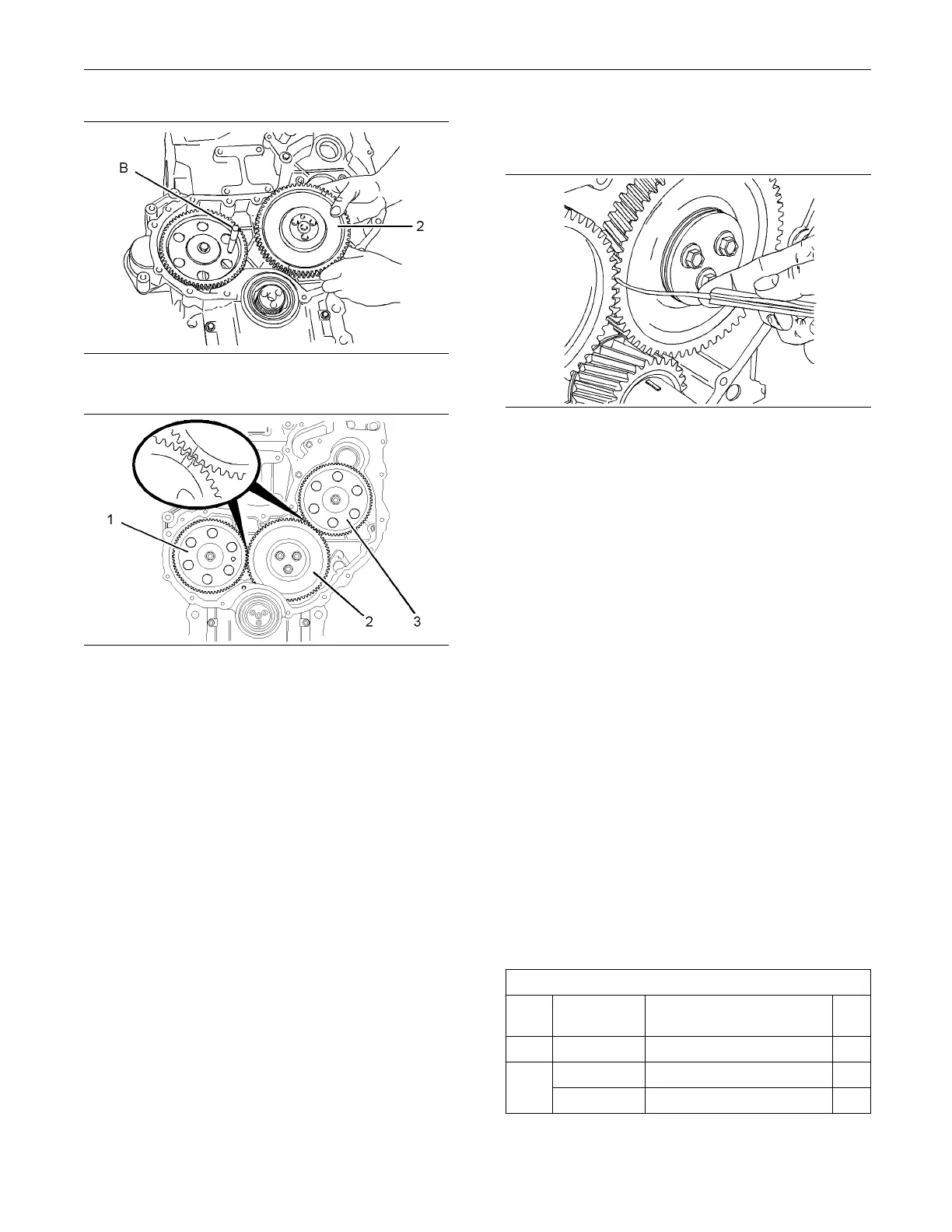
g01337905
Illustration 165
Typical exam p le
g01335384
Illustration 166
Alignment of timing marks
6. Install idler gear (2). Ensure that the timing marks
on gears (1) and (2) are in alignment and that the
mesh of the gears is correct. Refer to Disassembly
and Assembly, “Idler Gear - Remove and Install”.
Check the end play of the idler gear. Refer to
Specifications, “Gear Group (Front)” and refer to
Disassembly and Assembly, “Idler Gear - R emove
and Install” for further information.
7. Tighten bolt (6) for the camshaft gear to a torque
of 95 N·m (70 lb ft). Check the end play of the
camshaft gear. Refer to Specifications, “Camshaft”
for more information.
8. Ensure that the fuel injection pump is locked in
the correct position. Refer to Disassembly and
Assembly, “Fuel Injection Pump - Install”.
9. Install fuel injection pump gear (3). Ensure that the
timing marks on gears (2) and (3) are in alignment.
See Illustration 166. Ensure that the mesh of
the gears is correct. Refer to Disassembly and
Assembly, “Fuel Injection Pump Gear - Install” for
more information.
10. Remove Tooling (B) and (C). Install plug (4) into
hole (Y) in the c
ylinder block. Refer to Illustration
162.
g01335426
Illustration 167
Checking backlash
11. Ensure that the backlash for gears (1), (2) and (3)
is within specified values. Refer to Specifications,
“Gear Group (Front)” for further information.
12. Lubricate each gear with clean engine oil.
13. Adjust the engine valve lash. Refer to System
Operation, Testing and Adjusting, “Engine Valve
Lash - Inspect/Adjust”.
End By:
a. Install the front cover. Refer to Disassembly and
Assembly, “Front Cover - Remove and Install”.
b. Install the front cover. Refer to Disassembly and
Assembly, “Front Cover - Remove and Install”.
i02654520
Idler Gear
-Remove
Removal Procedure (Standard Idler
Gear)
Table 40
Required Tools
Tool
Part
Number
Part Name Qty
A
27610212
Camshaft Timing Pin
1
27610286
Crankshaft Timing Pin
1
B
27610287
Adapter 1

 Loading...


