174 KENR6932
Disassembly a nd Assembly Section
7. If necessary, follow Steps 7.a and 7.b in order to
remove the tens
ioner (3) from mounting bracket
(2).
a. Remove bolt (4
) that secures tensioner (3) to
mounting bracket (2).
b. Remove tensio
ner (3) from mounting bracket
(2).
Installation Procedure
Table 82
Required Tools
Tool Part
Number
Part Description
Qty
A
-
Locking Pin
(Ø 8mm by 85 mm)
1
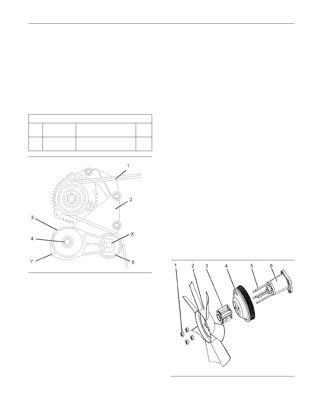
g011568 50
Illustration 351
Typical exam p le
1. If the tensioner was previously removed, follow
Steps 1.a through 1.c in order to install the
tensioner.
a. Align the dowel in back of tensioner (3) with the
hole in mounting bracket (2).
b. Install tensioner (3) to mounting bracket (2).
c. Install bolt (4). Tighten the bolt to a torque of
45 ± 5 N·m (33 ± 3 lb ft).
2. Install a suitable square drive tool into hole (X) in
tensioner (1). From the front of the engine, turn
thetoolinaclockwisedirection.
3. Insert Tooling (A) into hole (Y). Release the
pressure on the
square drive tool.
4. Install alternator belt (1). Ensure that the alternator
belt is center
ed on pulley (5). A used alternator
belt should be installed in the original direction of
rotation.
Note: The ribs on the alternator belt must be located
into the ribs of all pulleys.
5. From the front of the engine, turn the square drive
tool in a clockwise direction. Release pressure on
To ol i ng ( A ).
Remove Tooling (A) from hole (Y).
6. Release the pressure on the square drive tool until
the alternat
or belt is tensioned. Remove the tool
from hole (X).
Note: The ten
sioner should be at the nominal
position.
7. If the engin
e has fan guards, install the fan guards.
i02654363
Fan - Remove an d Install
Removal Procedure
Start By:
a. Remove the Alternator Belt. Refer to Disassembly
and Assembly, “Alternator Belt - Remove and
Install”.
g01341776
Illustration 352
Typical example

 Loading...


