154 KENR6932
Disassembly a nd Assembly Section
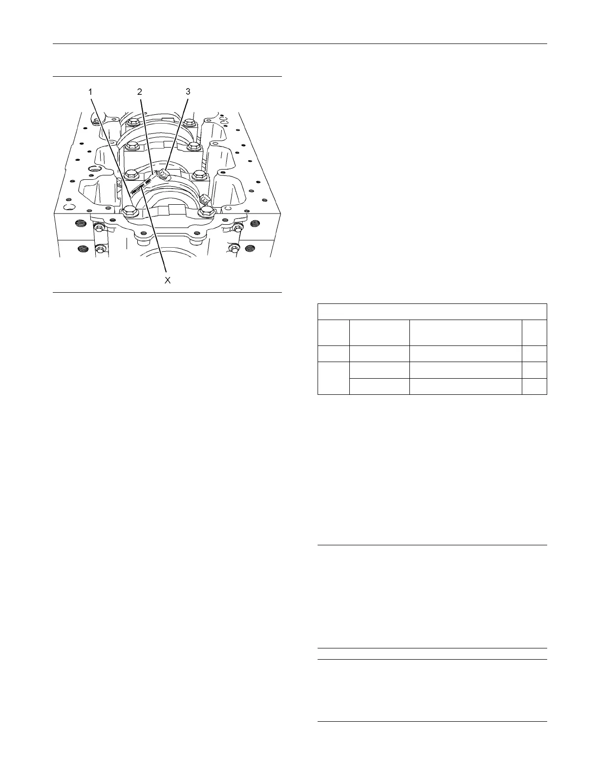
g01341291
Illustration 308
8. Install connecting rod cap (2) to connecting rod
(5).
Note: Ensure that etched number (X) on connecting
rod cap (2) matches etched number (X) on
connecting rod (5). Ensure the correct orientation of
the connecting rod cap. The locating tab for the upper
bearing shell and the lower bearing shell should be
on the same side.
9. Install new bolts (1) to the connecting rod. Tighten
theboltsevenlytoatorqueof18N·m(13lbft).
Note: Do not reuse the old bolts in order to secure
the connecting rod cap.
10. Tighten the bolts evenly to a torque of 70 N·m
(52 lb ft).
11. Turn the bolts through an additional 120 degrees.
UseTooling(B)toachievethecorrectfinal torque.
12. Ensure that the installed connecting rod assembly
has tactile side play. Rotate the crankshaft in order
to ensure that there is no binding.
13. Repeat Steps 2 through 12 for the remaining
connecting rod bearings.
Note: If all connecting rod bearings require
replacement the procedure can be carried out on
two cylinders at the same time. The procedure can
be carried out on the following pairs of cylinders. 1
with6,2with5,and3with4.Ensure that both
pairs of the connecting rod bearings are installed
before changing from one pair of cylinders to
another pair of cylinders.. Refer to Disassembly
and Assembly, “Connecting Rod Bearings - Install”.
14. If the glow plugs were removed, install the glow
plugs. Ref to Di
sassembly and Assembly, “Glow
Plugs - Remove and Install”
End By:
a. Install the engine oil pump. Refer to Disassembly
and Assembly,
“Engine Oil Pump - Install”.
i02654465
Crankshaft Main Bearings -
Remove and Ins tall
(Crankshaft in p osition)
Removal Procedure
Table 74
Required Tools
Tool
Part
Number
Part Name Qty
A
1
21825576
Crankshaft Turning Tool
1
27610291
Barring Device Housing 1
A
2
27610289
Gear 1
Start By:
a. Remove the en
gine oil pump. Refer to
Disassembly and Assembly, “Engine Oil Pump
- Remove”.
b. Remove the crankshaft rear seal. Refer to
Disassembly and Assembly, “Crankshaft Rear
Seal - Remov
e”.
Note: EitherTooling(A)canbeused.UsetheTooling
that is most
suitable.
NOTICE
This procedure must only be used to remove and in-
stall the main bearing shells with the crankshaft in po-
sition.
The removal procedure and the installation procedure
must be com
pleted for each pair of main bearing shells
before the next pair of main bearing shells are re-
moved.
NOTICE
Keep all parts clean from contaminants.
Contaminants may cause rapid wear and shortened
component life.

 Loading...


