KENR6932 121
Disassembly and Assembly Section
NOTICE
Failure to ensure that ALL valve bridges are correct-
ly seated onto t
he valve stems will cause interference
between the pistons and the valves, resulting in dam-
age to the engine.
3. Install valve bridges (4) to the cylinder head.
Note: Install
used valve bridges in the original
location and in the original orientation. Ensure that the
valve bridges are correctly seated on t he valves. New
valve bridges
may be installed in either orientation.
4. Clean the pushrods. Inspect the pushrods for
wear or damage
. Replace any pushrods that are
worn or damaged.
5. Apply clean e
ngine lubricating oil to both ends of
pushrods (3). Install the pushrods to the engine
with the cup upward.
Note: Ensure that pushrods (3) are installed in the
original location and that the ball end of each pushrod
is correctl
y seated in the valve lifters.
g01340040
Illustration 238
6. Ensure that the rocker shaft assembly is clean
and free from wear or damage. Install torx screws
(1) in the rocker shaft.
g01340044
Illustration 239
7. Position rocker shaft assembly (2) onto the
cylinder head. The retaining clip (6) should face
the front of the engine.
Note: Ensure that adjustment screws (5) are properly
seated in ends of pushrods (3).
8. Gradually tighten torx screws (1).
Note: To avoid distortion of rocker shaft assembly
(2), tighten the torx screws in the center first. Work
toward the out
side of the rocker shaft assembly.
Tighten torx screws (1) to a torque of 35 N·m
(26 lb ft).
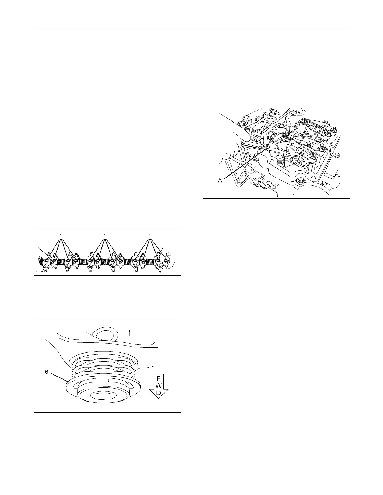
g01340045
Illustration 240
9. Use Tooling (A) in order to check the valve lash.
Refer to System Operation, Testing and Adjusting,
“Engine Valve Lash - Inspect/Adjust”. If necessary,
adjust the valve lash. Refer to System Operation,
Testing and Adjusting, “Engine Valve Lash -
Inspect/Adjust” for the correct procedure.
End By:
a. Install the valve mechanism cover. Refer to
Disassembly and Assembly, “Valve Mechanism
Cover - Remove and Install”.
i02654475
Cylinder Head - Remo ve
Removal Procedure
Start By:
a. If necessary, remove the secondary fuel filter and
the fuel filter base. Refer to Disassembly and
Assembly, “Fuel Filter Base - Remove and Install”.
b. If necessary, remove the fuel priming pump and
the primary fuel filter. Refer to Disassembly and
Assembly, “Fuel Priming Pump - Remove and
Install”.
c. Remove the exhaust manifold. Refer to
Disassembly and Assembly, “Exhaust Manifold
- Remove and Install”.

 Loading...


