KENR6932 175
Disassembly and Assembly Section
1. Remove locking nuts (1).
2. Remove fan (2 ).
Note: Note the o
rientation of the fan.
3. Remove fan adapter (3).
4. Remove fan pulley (4).
5. If necessary,
remove studs (5) from fan drive (6).
Installation
Procedure
1. Ensure that all the components are free from wear
or damage. If n
ecessary, replace any components
that are worn or damaged.
g01341776
Illustration 353
Typical exam p le
2. If necessary, install studs (5) to fan drive (6).
Tighten studs (5) to a torque of 11 N·m (97 lb in).
3. Install fan pulley (4).
4. Install fan adapter (3).
5. Install fan (2).
Note: Ensure that the fan is correctly oriented.
6. Inspect the condition of locking nuts (1). If
necessary, replace the locking nuts. Install locking
nuts (1). Tighten locking nuts (1) to a torque of
22 N·m (16 lb ft).
End By:
a. Install the Alternator Belt. Refer to Disassembly
and Assembly, “Alternator Belt - Remove and
Install”.
i02654491
Fan Drive - R emove an d In stall
Removal Proced
ure
Start By:
a. Remove the fan. Refer to Disassembly and
Assembly, “Fan - Remove and Install”.
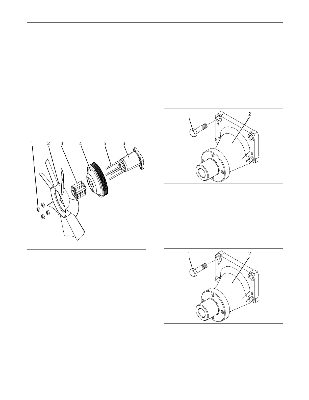
g01341855
Illustration 354
1. Remove bolts (1) from fan drive (2).
Note: Identify the orientation and the position of the
fan drive.
2. Remove fan drive (2).
Installation Procedure
g01341855
Illustration 355
1. Check the f
an drive for wear or damage. If the fan
drive is worn or damaged, replace the fan drive.
2. Install f
an drive (2).
3. Install bolts (1). Ti ghten the bolts to a torque of
44 N·m (32
lb ft).

 Loading...


