KENR6932 17
Disassembly and Assembly Section
10. Loosely connect the nuts at both ends of fuel
injection line
(2), to electronic unit injector (1) and
to the appropriate port in fuel manifold (4). Ensure
that the ends of the fuel injection line are correctly
seated in the e
lectronic unit injector and in the
fuel manifold.
11. Use Tooling (
A) to tighten the nuts on fuel injection
line(2)toatorqueof30N·m(22lbft).Ensurethat
the dust seal is seated correctly against seal (5).
12. Follow Steps 8 through 11 in order to install the
remaining fuel injection lines.
13. Install new clamps (3) to the fuel injection lines.
Ensure that the clamps are fully closed in order to
retain the fu
el injection lines.
Note: Ensure that fuel injection lines do not contact
any other en
gine component.
14. Restore the fuel supply.
15. Restore the electrical supply.
16. If the engin
e was equipped with a cover over the
fuel system this will need to be installed.
17. Remove the a
ir from the fuel system. Refer
to Operations and Maintenance Manual, “Fuel
System - Prime”.
i02654505
Fuel Injection Pu mp - Remove
Removal Procedure
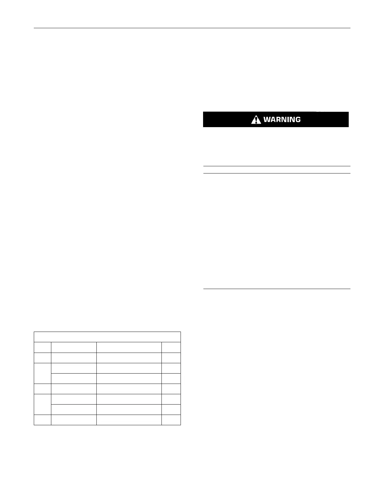
Table 3
Required Tools
Tool Part Number Part Name Qty
A
21825576
Crankshaft Turning Tool 1
27610291
Barring De
vice Housing
1
A
27610289
Gear
1
B 27610212
Camshaft Timing Pin
1
27610286
Crankshaft Timing Pin
1
C
27610287
Adapter 1
D
-
Cap 2
Start By:
a. If necess
ary, remove the fuel filter base. Refer to
Disassembly and Assembly, “Fuel Filter Base -
Remove and Install”.
b. If necessary, remove the fuel priming pump. Refer
to Disassembly
and Assembly, “Fuel Priming
Pump - Remove”.
c. Remove the fro
nt cover. Refer to Disassembly
and Assembly, “Front Cover - Remove and Install”.
Note: Either T
ooling (A) can be used. Use the Tooling
that is most suitable.
Contact with high pressure fuel may cause fluid
penetration and burn hazards. High pressure fu-
el spray may c
ause a fire hazard. Failure to fol-
low these inspection, maintenance and service in-
structions may cause personal injury or death.
NOTICE
Ensure that all adjustments and repairs that are
carried out to the fuel system are performed by
authorised personnel that have the correct train-
ing.
Before begining ANY work on the fuel system, re-
fer to Operation and Maintenance Manual, “Gen-
eral Hazard Information and High Pressure Fuel
Lines” for safety information.
Refer to System Operation, Testing and Adjusting,
“Cleanliness of Fuel System Components” for de-
tailed information on the sta ndards of cleanliness
that must be observed during ALL work on the fu-
el system.
1. Isolate the fuel supply.
2. Isolate the electrical supply.
3. Use Tooling (A) in order to rotate the crankshaft
so that number one piston is at top dead center
on the compression stroke. Refer to System
Operation, Testing and Adjusting, “Finding Top
Centre Position for No.1 Piston”.
4. Use Tooling (B) in order to lock the camshaft in
the correct position. Use Tooling (C) in order to
lock the crankshaft in the correct position. Refer to
Disassembly and Assembly, “Gear Group (Front)
- Remove” for the correct procedure.
5. Remove the backlash from the fuel pump gear.
Lock the fuel injection pump in the correct
position and remove the fuel pump gear. Refer to
Disassembly and Assembly, “Fuel Pump Gear -
Remove and Install” for the correct procedure.

 Loading...


