40 KENR6932
Disassembly a nd Assembly Section
g01335754
Illustrat
ion 70
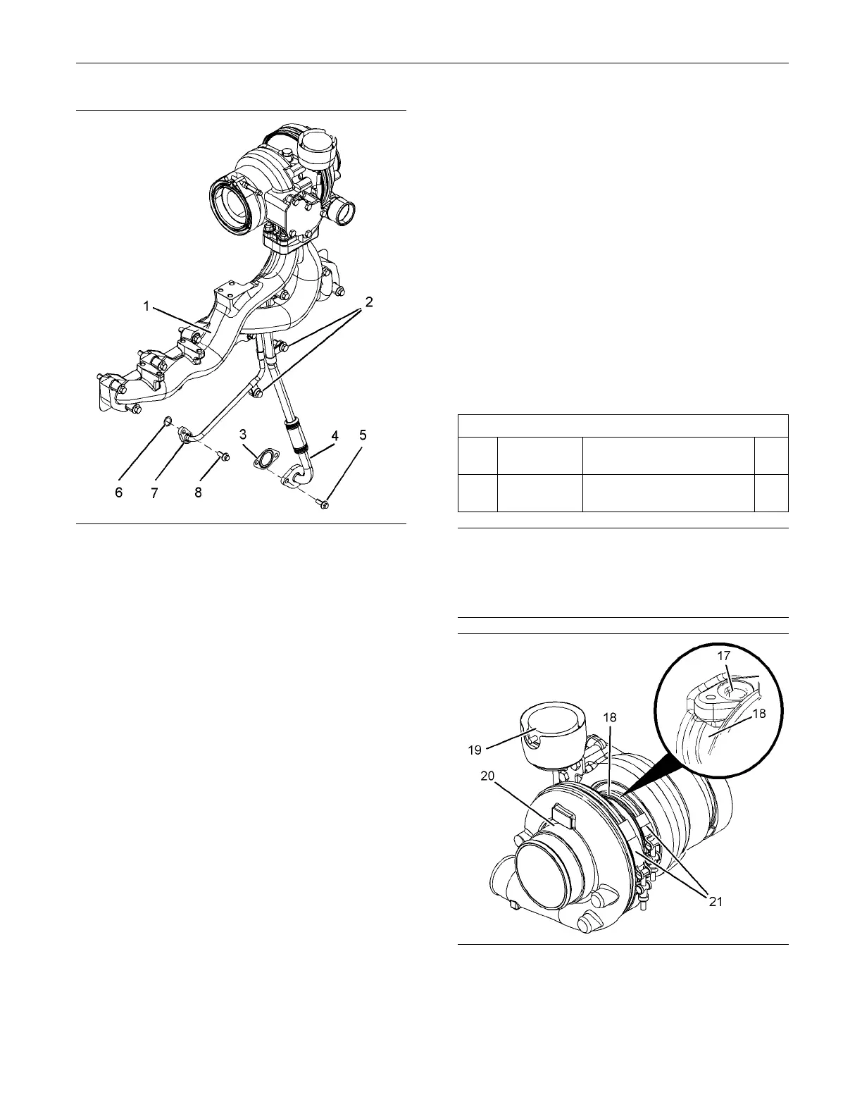
15. Install exhaust manifold (1) and the assembly of
the turbo
charger to the cylinder head. Refer to
Disassembly and Assembly, “Exhaust Manifold -
Remove and Install” for the correct procedure.
16. Install bolt (8) finger tight. Ensure that tube
assembly (7) fits correctly.
17. Position a new joint (3) between the flange of
tube assembly (4) and the cylinder block. Install
bolts (5
) finger tight.
18. If a new turbocharger has been installed, check
that the
orientation of bearing housing (18) is
correct. If the orientation of the bearing housing is
not correct, rotate the bearing housing until tube
assembl
ies (4) and (7) fit correctly. Tighten band
clamps (21) to a torque of 13 N·m (9.6 lb ft).
19. Tighten
banjo bolt (9) to a torque of 20 N·m
(14 lb ft). Tighten bolt (5) and (8) to a torque of
22 N·m (16 lb ft).
20. Install the bolts for tube clips (2) to the cylinder
block. Tighten bolt (2) to a torque of 44 N·m
(32 lb f
t).
21. If the turbocharger has an exhaust elbow, install
the exh
aust elbow. Refer to Disassembly and
Assembly, “Exhaust Elbow - Remove and Install”.
22. Connect the exhaust pipe.
23. If the turbocharger has a remote wastegate
solenoid, connect the hose for the solenoid to the
turbocharger
.
24. Connect the air inlet hose and connect the air
outlet hose to
the turbocharger.
i02654361
Turbocharger - Install
(Side Mounted Turbocharger)
Installation Procedure
Table 12
Required Tools
Tool
Part
Number
Part Description
Qty
A 21820221
POWERPART
Rubber Grease
1
NOTICE
Keep all parts clean from contaminants.
Contaminants may cause rapid wear and shortened
component life.
g01335496
Illustration 71
Typical example

 Loading...


