KENR6932 39
Disassembly and Assembly Section
2. Test the was tegate actuator (19) for correct
operation. Ref
er to System Operation, Testing and
Adjusting, “Turbocharger Inspect”. If the wastegate
actuator is damaged or the wastegate actuator
does not opera
te within the specified limits, the
wastegate actuator must be replaced. Refer to
Disassembly a nd Assembly, “Turbocharger -
Dissassembl
e” and refer to Disassembly and
Assembly, “Turbocharger - Assemble” for more
information.
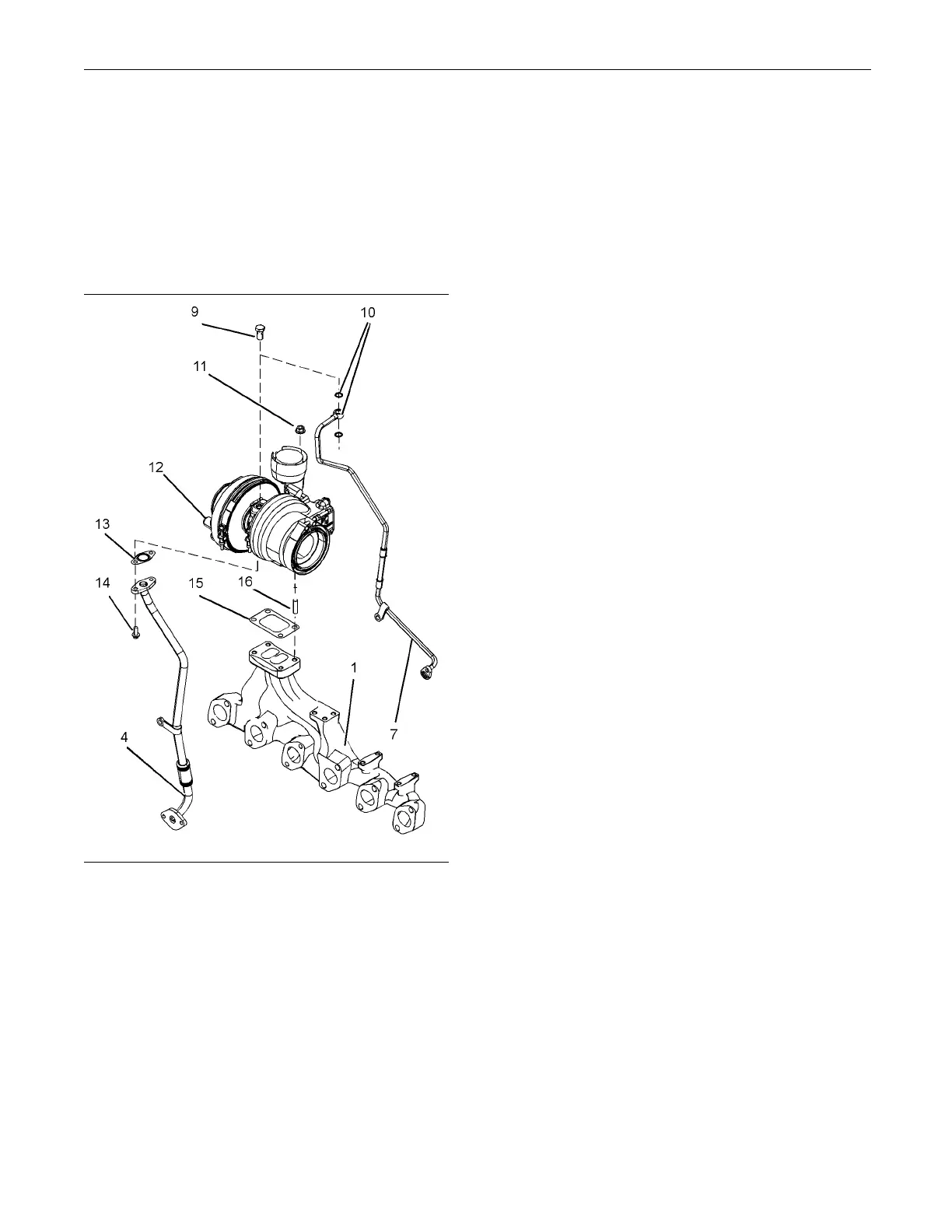
g01335756
Illustration 69
3. Clean the mating surfaces of the exhaust manifold
(1). If necessary, install studs (16) to the exhaust
manifold. Tighten the studs to a torque of 18 N·m
(13 lb ft).
Note: Support the exhaust manifold during
installation of the turbocharger.
4. Install a new joint (15) to exhaust manifold (1).
5. Position turbocharger (12) on exhaust manifold
(1).
Note: Ensure that the turbocharger is correctly
oriented.
6. Install nuts (11). Tighten the nuts to a torque of
44 N·m (32 lb ft)
.
7. If a new turbocharger is installed, bearing
housing (18) a
nd compressor housing (20) must
be oriented to the correct positions. Refer to
Illustration 68. Follow Steps 7.a through 7.d
in order to or
ient the bearing housing and the
compressor housing.
a. Loosen band c
lamps (21) sufficiently in order
to allow the housings to rotate.
Note: If the b
and clamps are damaged, replace the
band clamps.
b. Carefully tu
rn bearing housing (18) until the
port for oil feed (17) is upward.
c. Rotate compr
essor housing (20) until the
compressor outlet is in the correct position.
Refer to the turbocharger that was originally
installed f
or the correct orientation.
d. Ensure that band clamps (21) are correctly
oriented. R
efer to the turbocharger that was
originally installed for the correct orientation.
Tighten the band clamps finger tight.
8. Ensure that tube assemblies (4) and (7) are clean
and free from damage. Replace any damaged
component
s.
9. Position a new joint (13) and bolts (14) onto tube
assembly (
4).
10. Install tube assembly (4) to turbocharger (12).
Tighten b
olts (14) finger tight.
11. Remove the plug from oil inlet port (17). Refer to
Illustra
tion 68. Lubricate the turbocharger bearings
with clean engine oil through the oil inlet port.
Rotate the wheel of the compressor several times
in order t
o lubricate the bearings.
12. Install banjo bolt (9) and new sealing washers
(10) to tu
be assembly (7).
13. Use Tooling (A) in order to lubricate a new O-ring
seal (6).
Install O-ring seal (6) to tube assembly
(7). Refer to Illustration 70.
14. Install
tube assembly (7) to turbocharger (12).
Tighten banjo bolt (9) finger tight.

 Loading...


