KENR6932 183
Disassembly and Assembly Section
g01342054
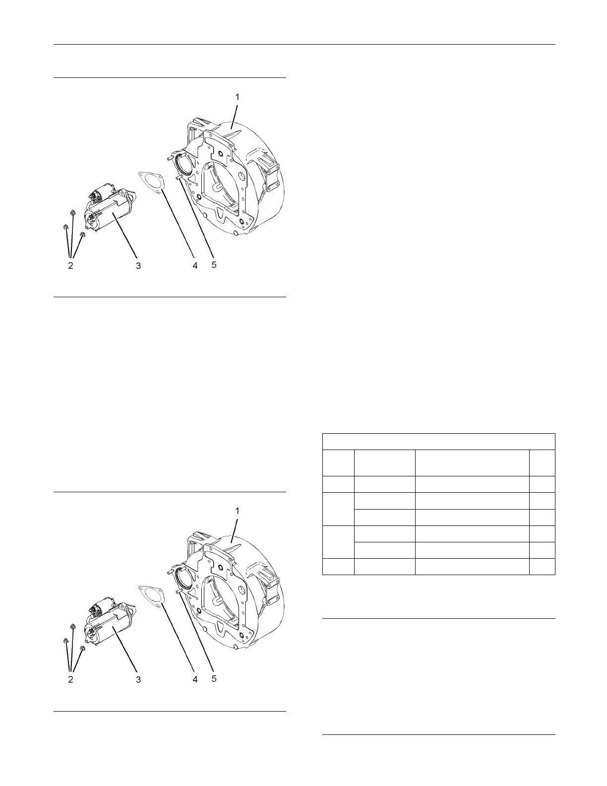
Illustration 370
Typical exam p le
3. Disconnect the harness assembly from the electric
starting motor and the solenoid.
4. Remove nuts (2) for electric starting motor (3).
5. Remove electric starting motor (3).
6. If a joint is installed, remove joint (4).
7. If necessary, remove studs (5) from flywheel
housing (1).
Installation Procedure
g01342054
Illustration 371
Typical exam p le
1. If necessary, install studs (5) into flywheel housing
(1).
2. If necessary, install a new joint (4) onto the studs
in flywheel hou
sing (1).
3. Position electric starting motor (3) onto the studs
in flywheel hou
sing (1).
4. Install nuts (2).
TightenM10nutstoatorqueof44±11N·m
(32±8lbft).
Tighten M12 nuts to a torque of 78 ± 19.5 N·m
(57 ± 14 lb ft).
5. Connect the harness assembly to the electric
starting motor and the solenoid.
6. Connect the battery.
i02654446
Air C om pressor - Remove and
Install
Removal Procedure
Table 83
Required Tools
Tool
Part
Number
Part Name Qty
A
1
21825576
Crankshaft Turning Tool
1
27610291
Barring Device Housing 1
A
2
27610289
Gear 1
27610286
Crankshaft Timing Pin 1
B
27610287
Adapter 1
C
-
Puller (Three Leg)
1
Note: EitherTooling(A)canbeused.UsetheTooling
that is most suitable.
NOTICE
Care must be taken to ensure that fluids are contained
during performance of inspection, maintenance, test-
ing, adjusting and repair of the product. Be prepared to
collect the fluid with suitable containers before open-
ing any compartment or disassembling any compo-
nent containing fluids.
Dispose of all fluids according to local regulations and
mandates.

 Loading...


