30 KENR6932
Disassembly a nd Assembly Section
i02654481
Electron ic Unit Injector - Install
Installation P
rocedure
Table 9
Required Tools
Tool Part
Number
Part Descripti
on
Qty
B
27610307
T40 Torx Socket 1
GE50028 Vacuum Pump 1
D
GE50030
Tube
7.9 mm (0.31 inch)
Outside Diameter
1
E
27610294
Injector Pipe Nut Tool 1
F
27610296
Torque Wrench 1
NOTICE
Ensure that all adjustments and repairs that are
carried out to the fuel system are performed by
authorised personnel that have the correct train-
ing.
Before begining ANY work on the fuel system, re-
fer to Operation and Maintenance Manual, “Gen-
eral Hazard Information and High Pressure Fuel
Lines” for safety information.
Refer to Systems Operation, Testing and Adjust-
ing Manual, “Cleanliness of Fuel System Compo-
nents” for detailed information on the standards
of cleanliness that must be observed during ALL
work on the fuel system.
NOTICE
Care must be taken to ensure that fluids are contained
during performance of inspection, maintenance, test-
ing, adjusting and repair of the product. Be prepared to
collect the fluid with suitable containers before open-
ing any compartment or disassembling any compo-
nent containing fluids.
Dispose of all fl uids according to local regulations and
mandates.
NOTICE
Use a deep socket in order to remove the electrical
connections from the electronic unit injectors. Use of
incorrect tooling will result in damage to the electronic
unit injectors.
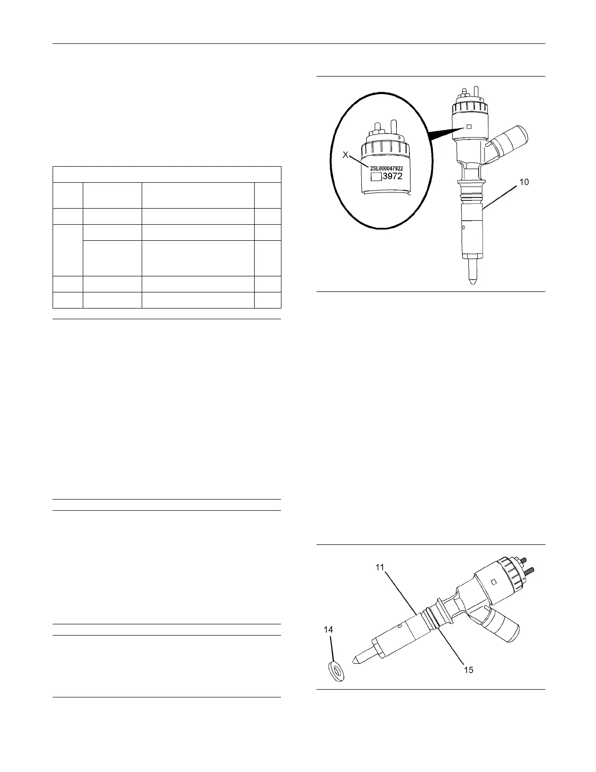
g01341874
Illustration 51
Typical calibration code
1. If a replacement electronic unit injector is installed,
the correct injector trim file must be programmed
into the electronic control module. Refer to
Troubleshooting, “Injector Trim File” for more
information. The code that is required to obtain
the injector trim file is located at position (X).
Note: Record code (X) before the electronic unit
injector is installed.
2. Use Tooling (D) in order to remove any fuel from
the cylinder.
Note: Evacuate as much fuel as possible from the
cylinder before installing the electronic unit injector.
3. Ensure that the fuel inlet port of the electronic unit
injector is capped. Ensure that the electronic unit
injector is clean.
g01255701
Illustration 52

 Loading...


