KENR6932 29
Disassembly and Assembly Section
g01247489
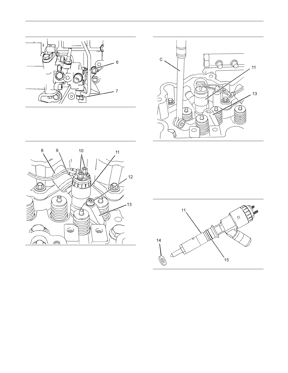
Illustration 47
Typical exam p le
3. Loosen banjo bolt (7) sufficiently in order to allow
the fuel to drain from tube assembly (6).
g01255699
Illustration 48
4. Place a temporary identification mark on
connections (10) for harness assembly (9).
5. Use a deep socket to remove connections (10)
from electronic unit injector (11).
6. Use Tooling (B) in order to remove torx screw (12)
from clamp (13). Discard the torx screw.
7. Place a temporary identification mark on the
original electronic unit injector. The electronic unit
injector must be reinstalled in the original location
in the cylinder head.
g01255700
Illustration 49
8. Use Tooling (C) to pry beneath clamp (13) and free
electronic unit injector (11) from the cylinder head.
9. Remove electronic unit injector (11) and clamp
(13) from the cylinder head.
Note: Always handle electronic unit injectors with
care.
g01255701
Illustration 50
Typical example
10. Remove sealing washer (14). Ensure that the
sealing washer is removed from the cylinder head.
Remove O-ring seal (15) from the electronic unit
injector.
11. Repeat Steps 4 through 11 in order to remove the
remaining electronic unit injectors.

 Loading...


