178 KENR6932
Disassembly a nd Assembly Section
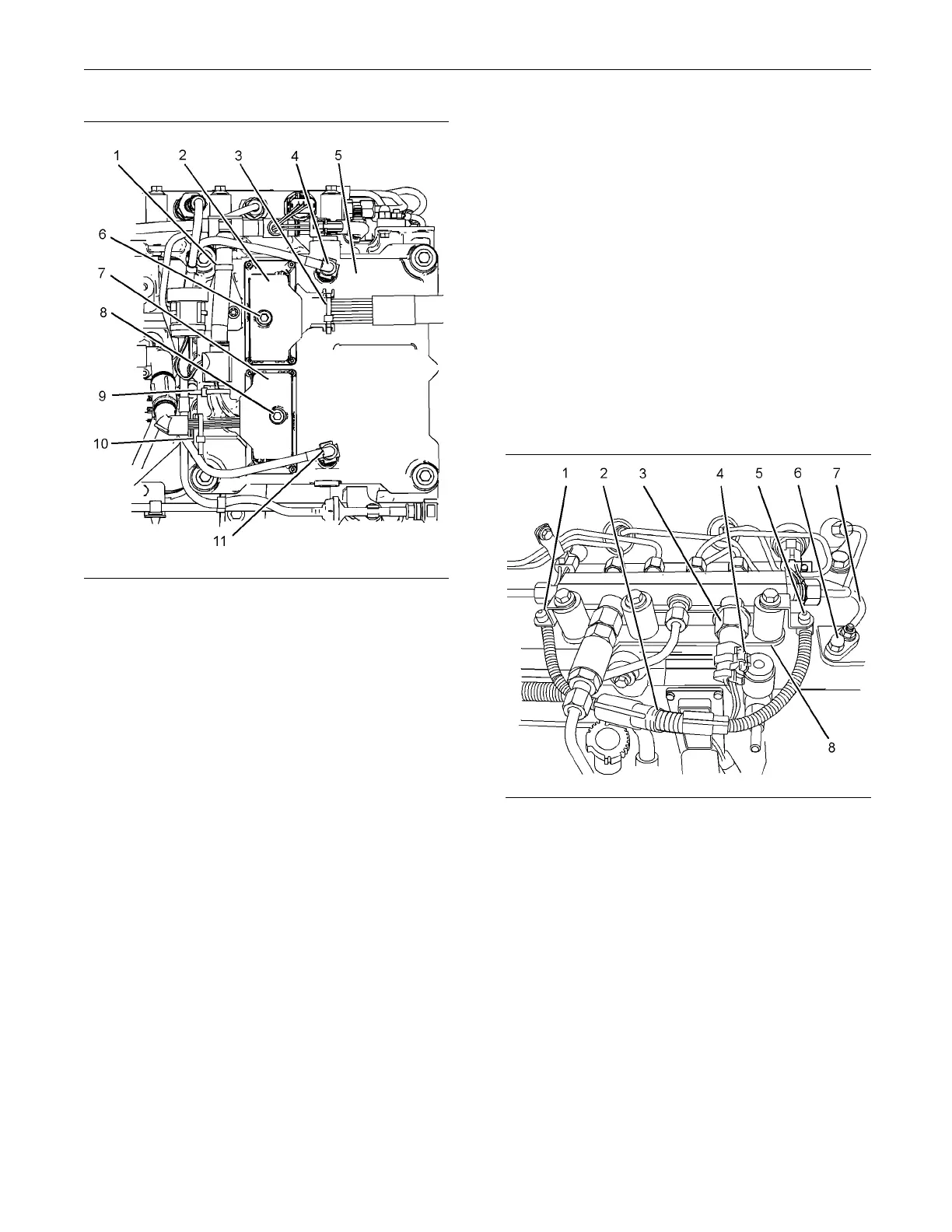
g01341877
Illustrat
ion 359
Typical exam p le
6. Remove the plugs from plastic tube assemblies
(4) and (11). If necessary, remove the caps from
the conne
ctors in the electronic control module.
Connect plastic tube assemblies (4) and (11).
7. Connect e
ngine wiring harness (7) to electronic
control module (5). Tighten the fastener (8) to a
torque of 5 N·m (3 lb ft).
Note: Caremustbetakeninordertoavoiddamageto
the connector pins during installation of the harness.
8. Position the assembly of the engine wiring harness
onto brackets (14) and (16). Use new cable straps
(1), (9)
and (10) in order to secure the harness
assembly to the brackets.
9. Connect
OEM wiring harness (2) to electronic
control module (5). Tighten fastener ( 6) to a torque
of 5 N·m (3 lb ft).
Note: Caremustbetakeninordertoavoiddamageto
the connector pins during installation of the harness.
10. Use a new cable strap (3) in order to secure the
harness assembly.
11. Restore the fuel supply to the engine.
12. Restor
e the electrical supply to the engine.
13. Remove the air from the fuel system. Refer to
Operation and M
aintenance Manual, “Fuel System
- Prime”.
i02654477
ECM Moun ting Bracket -
Remove and Ins tall
Removal Procedure
Start By:
a. Remove the electronic control module. Refer to
Disassembly
and Assembly, “Electronic Control
Module - Remove and Install”.
g01342045
Illustration 360
1. Follow Steps 1.a through 1.c in order to disconnect
engine wiring harness (2) .
a. Slide locking tab (4) into the unlocked position.
b. Disconnect harness assembly (2) from fuel
pressure sensor (3).
c. Cut cable straps (1) and (5). Position harness
assembly (2) so that the harness assembly is
clear of mounting bracket (8).
2. Disconnect wire (7) for the glow plugs. Remove
terminal insulator (6) from mounting bracket (8).
Refer to Disassembly and Assembly, “Glow Plugs
- Remove and Install” for the correct procedure.

 Loading...


