78 KENR6932
Disassembly a nd Assembly Section
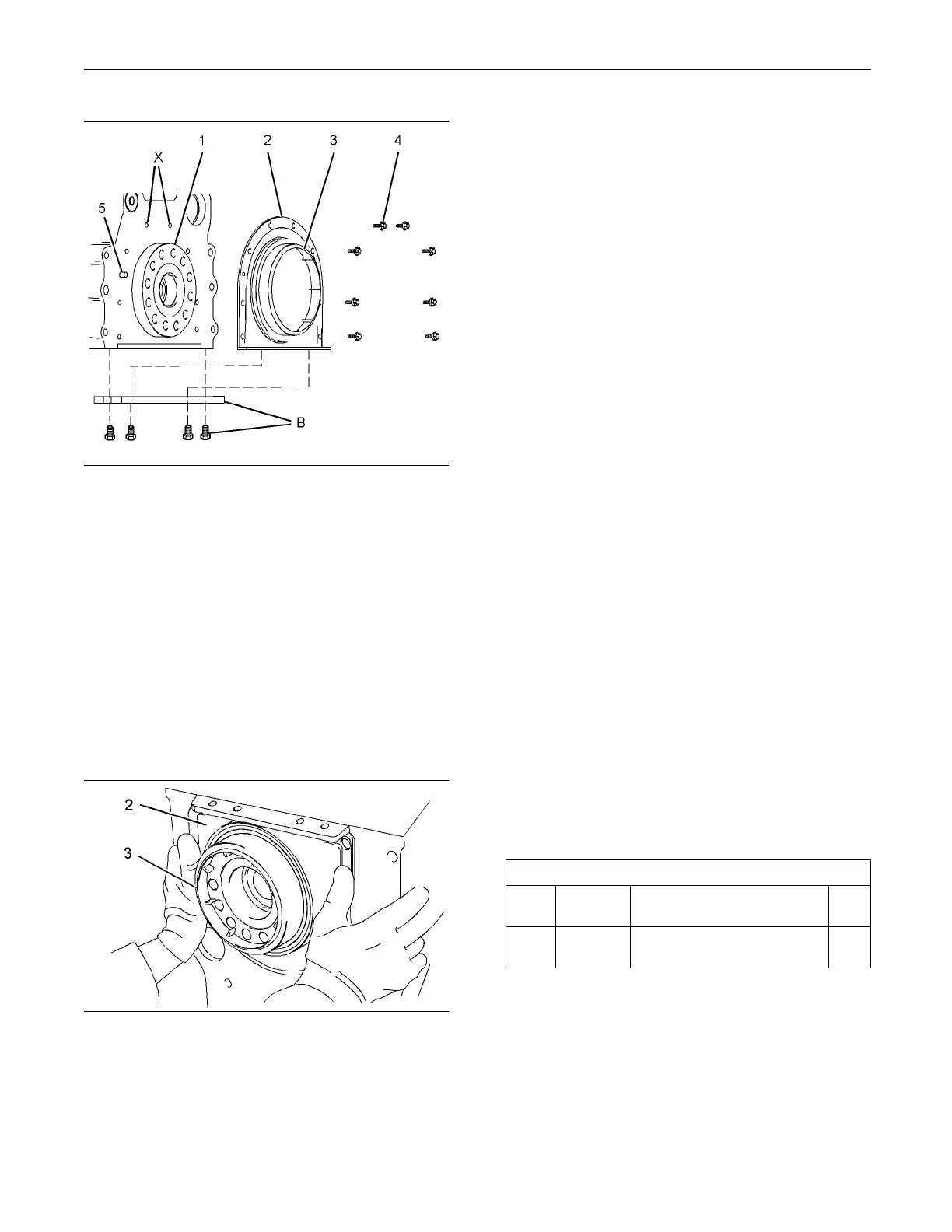
g01374593
Illustration 135
Typical exam p le
2. Ensure that crankshaft flange (1) is clean, dry and
free from damage.
3. Ensure that the mating surface of the cylinder
blockiscleananddry.
4. Ensure that plastic sleeve (3) is squarely installed
within new crankshaft rear seal (2).
Note: The plastic sleeve is included in order to
protect the lip of the seal as the crankshaft rear seal
is pushed over crankshaft flange (1). Do not attempt
to install a crankshaft rear seal without the plastic
sleeve.
g01337517
Illustration 136
Typical exam p le
5. Place the assembly of the crankshaft rear seal
over crankshaft flange (1). Align dowel (5) with the
slot in the crankshaft rear seal.
6. Ensure that plastic sleeve (3) is engaged on
crankshaft flan
ge (1). Push crankshaft rear seal
(2) squarely onto the crankshaft. Ensure that the
crankshaft rear seal is seated against the cylinder
block. During
this process, plastic sleeve (3) will
be forced out of the crankshaft rear seal. Discard
the plastic sleeve.
Note: Ensure that dowel (5) is engaged in the hole in
the crankshaft rear seal.
7. Install Tooling (C) to the cylinder block and to
crankshaft rear seal (2). Tighten the bolts to a
torque of 15 N
·m (11 lb ft).
8. Use Tooling (B) in order to install two Torx bolts (4)
to crankshaf
t rear seal (3) in position (X). Tighten
two Torx bolts (4) to a torque of 22 N·m (16 lb ft).
9. Use Tooling
(B) in order to install remaining Torx
bolts (4). Tighten all Torx bolts (4) to a torque of
22 N·m (16 lb ft).
10. Remove Tooling (C).
End By:
a. Install the engine oil pan plate. Refer to
Disassembl
y and Assembly, “Engine Oil Pan Plate
- Remove and Install”.
i02654494
Flywheel Housing - Remove
and Install
(Standard
Housing)
Removal Procedure
Table 28
Required T
ools
Tool
Part
Number
Part Descr
iption
Qty
A
-
Guide Stud
(M10 by 100 mm)
2
Start By:
a. Remove the flywheel. Refer to Disassembly and
Assembly, “Flywheel - Remove”.

 Loading...


