KENR6932 143
Disassembly and Assembly Section
g01340605
Illustration 289
Typical exam p le
10. If necessary, follow Steps 10.a through 10.c in
order to install the assembly of the dipstick tube.
a. Install a new seal (3) to the tube assembly (2).
b. Apply Tooling (B) to the nut (1). Install the tube
assembly to the engine oil pan.
Note: Ensure that the orientation of the tube
assembly is correct.
c. Tightenthenut(1)toatorqueof18N·m
(13 lb ft). Install the dipstick (not shown).
11. Fill the engine oil pan to the correct level. Refer
to Operation and Maintenance Manual, “Oil Filter
Change” for the procedure.
i02652928
Engine Oil
Pan Plate - Remove
and Install
(Aluminum Oil Pan)
Removal Procedure
Table 64
Required Tools
Tool
Part
Number
Part Description Qty
A
-
T40 Torx Socket
1
Start By:
a. Remove the engine oil pan. Refer to Disassembly
and Assembly, “Engine Oil Pan - Remove”.
b. Remove the flywheel housing. Refer to
Disassembly and Assembly, “Flywheel Housing
- Remove and Install”.
NOTICE
Keep all parts clean from contaminants.
Contaminants may cause rapid wear and shortened
component life.
NOTICE
Care must be taken to ensure that fluids are contained
during perform
ance of inspection, maintenance, test-
ing, adjusting and repair of the product. Be prepared to
collect the fluid with suitable containers before open-
ing any compar
tment or disassembling any compo-
nent containing fluids.
Dispose of all
fluids according to local regulations and
mandates.
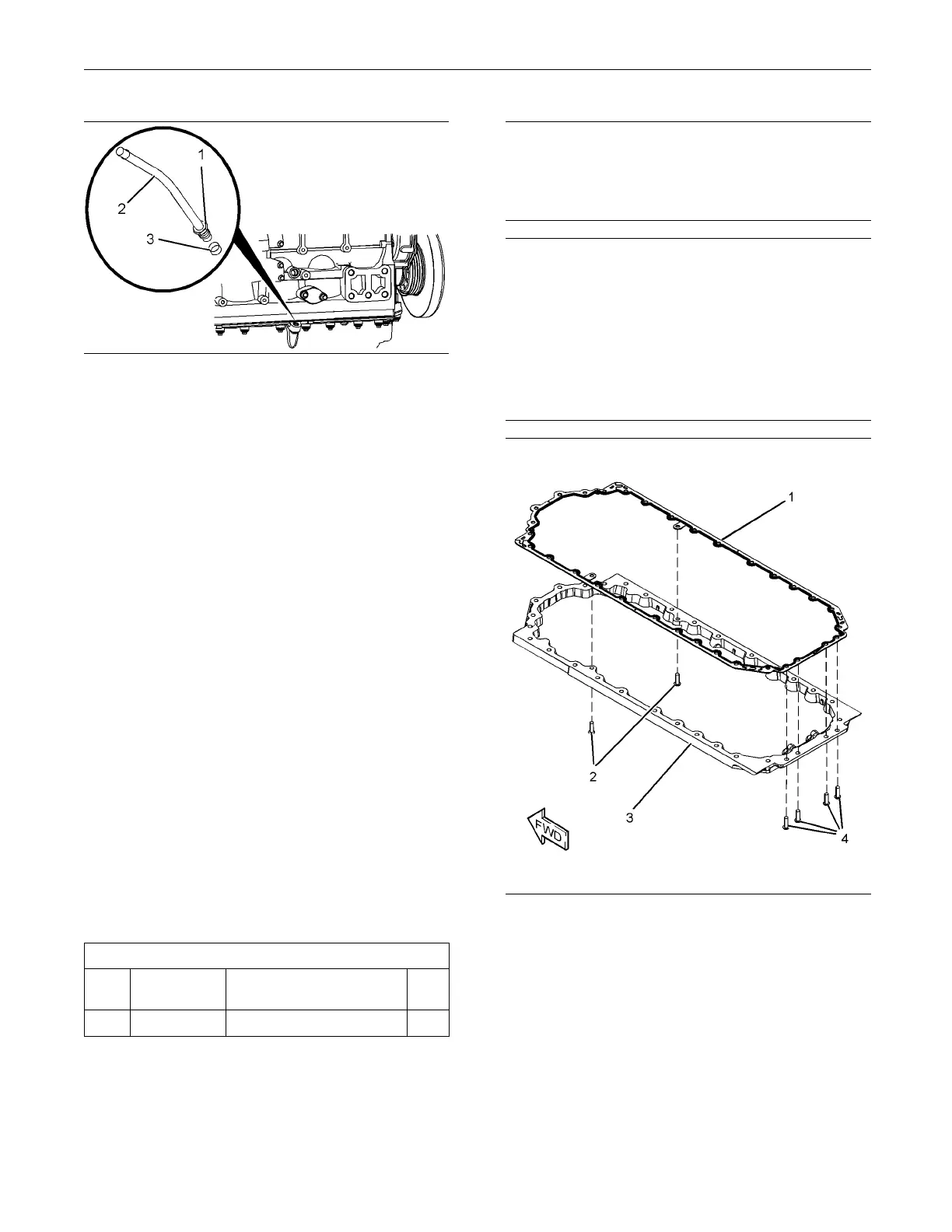
g01342059
Illustration 290
1. Remove isolating frame from the cylinder block.
Follow steps 1.a through 1.c in order to remove
the isolating frame from the cylinder block.
a. Support the isolating frame (3). Use Tooling (A)
to remove the torx screws (2) and (4).
b. Remove the isolating frame (3) from the
cylinder block.
c. Remove the joint (1).

 Loading...


