142 KENR6932
Disassembly a nd Assembly Section
g01340724
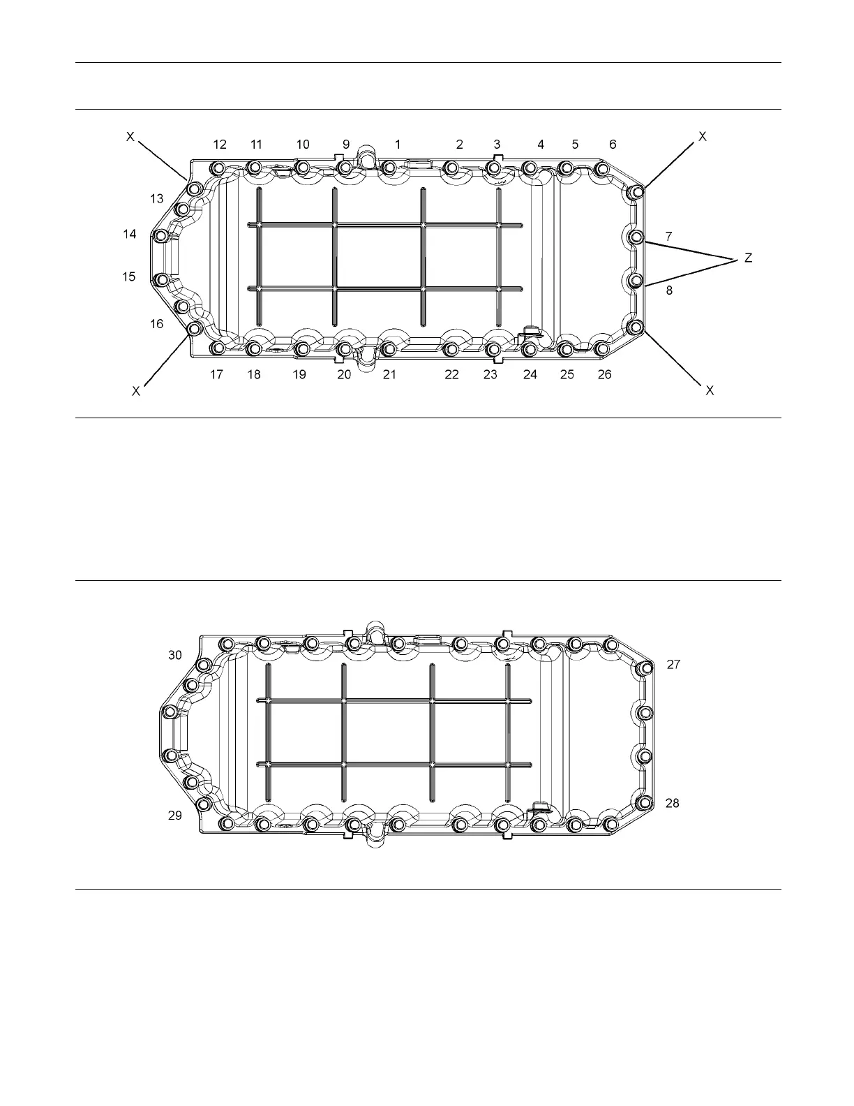
Illustration 287
(X) Position of guide studs.
(Z) P osition of short isolating screws.
6. Tighten the isolating screws to a torque of 22 N·m
(16 lb ft). Tighten the isolating screws in the
sequence that is shown in Illustration 287.
7. Remove Tooling (A).
g01340725
Illustration 288
8. Instal
l the four remaining isolating screws. Tighten
theisolatingscrewstoatorqueof22N·m(16lbft).
Tighten the isolating screws in the sequence that
is show
n in Illustration 288.
9. Instal
l a new O-ring seal (6) to the drain plug (5).
Install the drain plug (5) to the engine oil pan (7).
Refer to Illustration 286. Tighten the oil drain plug
to a tor
que of 34 N·m (25 lb ft).

 Loading...


