KENR6932 141
Disassembly and Assembly Section
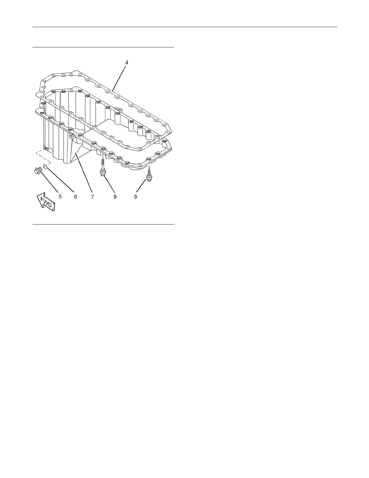
g01340606
Illustrat
ion 286
Typical exam p le
2. Ensure that the engine oil pan (7) is clean and free
from damage. Clean the isolating screws (8) and
(9). Insp
ect the isolating screws for deterioration
or damage. If necessary, replace the isolating
screws. If necessary, ensure that the mating
surface o
f the isolating frame is clean.
Note: The isolating screws must be replaced as a
complet
e set in order to ensure the correct clamping
of the engine oil pan.
3. Positio
n a new joint (4) onto the engine oil pan (7).
4. Install the isolating screws (8) and (9) to the
engine o
il pan. Do not install the isolating screws
(8) in positions (X). Refer to Illustration 285.
Note: Th
e isolating screws are held captive by the
joint.
5. Align th
e assembly of the engine oil pan with
Tooling (A). Install the assembly of the engine oil
pan to the isolating frame (12). Install the clip that
secure
s the breather hose in the correct position.

 Loading...


