164 KENR6932
Disassembly a nd Assembly Section
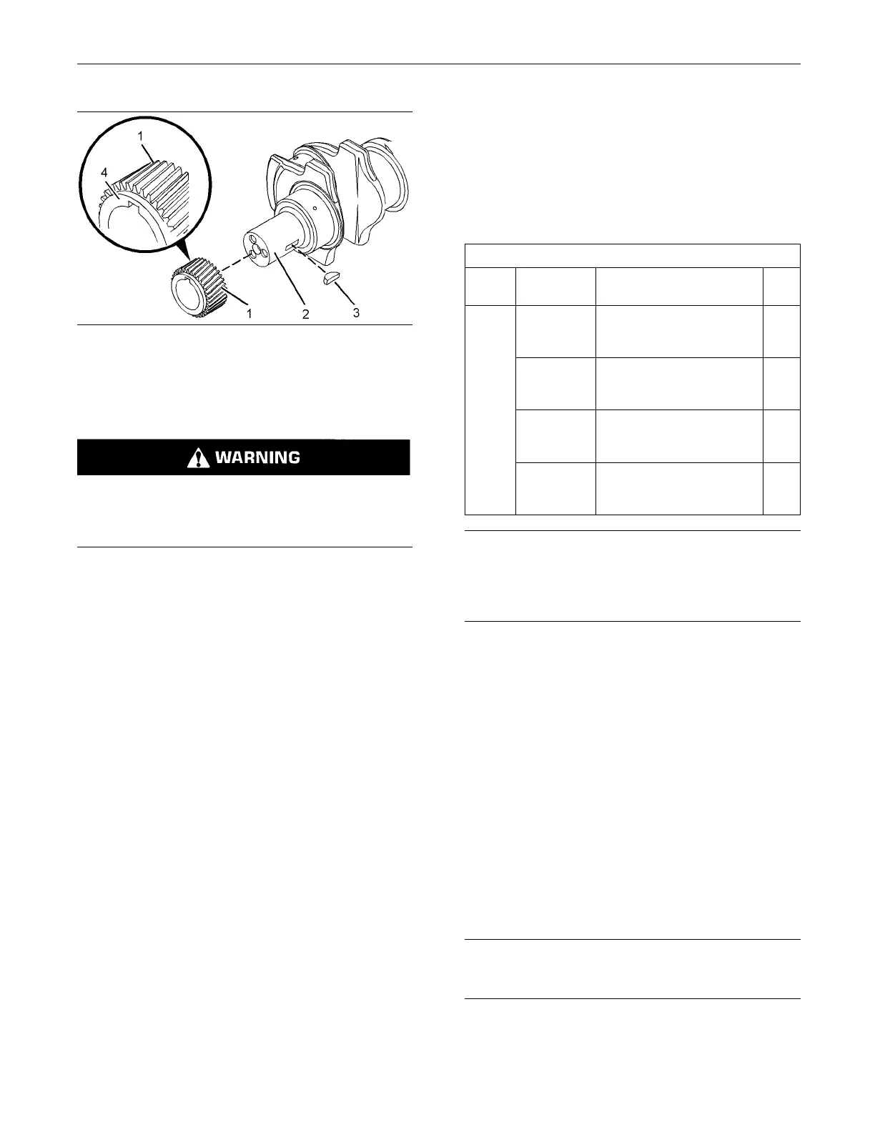
g01341493
Illustration 332
2. If necessary, install a new key ( 3) to crankshaft (2).
Note: The crankshaft gear may be a sliding fitonthe
crankshaft or an interference fit on the crankshaft.
Hot parts or hot components can cause burns or
personal injury. Do not allow hot parts or compo-
nents to contact your skin. Use protective clothing
or protective equipment to protect your skin.
3. If the crankshaft gear is a sliding fitonthe
crankshaft, align the keyway on crankshaft gear
(1) with key (3) in the crankshaft. Install crankshaft
gear (1) to crankshaft (2).
If the crankshaft gear is an interference fitonthe
crankshaft, heat crankshaft gear (1) in an oven to
150° ± 50°C (302° ± 90°F). Align the keyway on
crankshaft gear (1) with key (3) in the crankshaft.
Install crankshaft gear (1) to crankshaft (2).
Ensure that shoulder (4) of crankshaft gear (1) is
toward the front of the engine.
End By:
a. Install the front housing. Refer to Disassembly and
Assembly, “Housing (Front) - Install”.
b. Install the engine oil pump. Refer to Disassembly
and Assembly, “Engine Oil Pump - Install”.
i02748526
Bearing Clearance - Check
Measurement Pr
ocedure
Table 79
Required Tools
Tool
Part
Number Part Description Qty
-
Plastic Gauge (Green)
0.025 to 0.076 mm
(0.001 to 0.003 inch)
1
-
Plastic Gauge (Red)
0.051 to 0.152 mm
(0.002 to 0.006 inch)
1
-
Plastic Gauge (Blue)
0.102 to 0.229 mm
(0.004 to 0.009 inch)
1
A
-
Plastic Gauge (Yellow)
0.230to0.5
10 mm
(0.009 to 0.020 inch)
1
NOTICE
Keep all parts clean from contaminants.
Contaminants may cause rapid wear and shortened
component life.
Note: Perkins does not recommend the checking of
the actual c
learances of the bearing shells particularly
on small engines. This is because of the possibility
of obtaining inaccurate results and of damaging the
bearing she
ll or the journal surfaces. Each Perkins
bearing shell is quality checked for specificwall
thickness.
Note: The measurements should be within
specifications and the correct bearings should
be used. If
the crankshaft journals and the bores
for the block and the rods were measured during
disassembly, no further checks are necessary.
However, i
f the technician still wants to measure the
bearing clearances, Tooling (A) is an acceptable
method. Tooling (A) is less accurate on journals with
small dia
meters if clearances are less than 0.10 mm
(0.004 inch).
NOTICE
Lead wire
, shim stock or a dial bore gauge can dam-
age the bearing surfaces.
The techn
ician must be very careful to use Tooling (A)
correctly. The following points must be remembered:

 Loading...


