KENR6932 119
Disassembly and Assembly Section
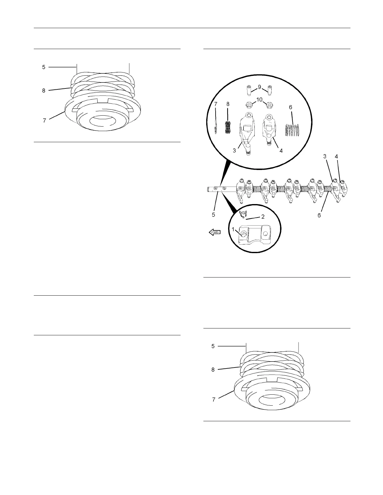
g01340048
Illustration 233
6. If necessary, remove retaining clip (7) and remove
spring (8) from the front end of rocker shaft (5).
7. If necessary, remove nuts (10) and adjusters
(9) from the rocker arms. Make a temporary
identification mark on each adjuster in order to
show the location.
Note: The components must be reinstalled in the
original location. Do not interchange components.
i02654537
Rocke r Sha
ft-Assemble
Assembly Procedure
NOTICE
Keep all parts clean from contaminants.
Contamina
nts may cause rapid wear and shortened
component life.
1. Ensure that all components are clean and free
from wear or damage. Refer to Specifications,
“Rocker Shaft” for more information. If necessary,
replace any components that are worn or
damaged.
g01340047
Illustration 234
2. If necessary, install nuts (10) and adjusters (9) to
rocker arm assemblies (3) and (4). If the original
adjusters are reused, ensure that the adjusters
are installed in the original positions.
g01340048
Illustration 235
3. Install retaining clip (7) and spring (8) to the front
end of rocker shaft (5).
4. Lubricate the bores of rocker arm assemblies (3)
and (4) and rocker shaft (5) with clean engine oil.

 Loading...


