KENR6932 9
Disassembly and Assembly Section
2. Position fuel filter base (1) on the mounting
bracket. Insta
ll bolts (3). Tighten the bolts to a
torque of 44 N·m (32 lb ft).
3. Remove the plu
gs from the plastic tube
assemblies. Remove the caps from the ports in
the fuel filter base.
NOTICE
Ensure that th
e plastic tube assemblies are installed
in the original positions. Failure to connect the plastic
tube assemblies to the correct ports will allow contam-
ination to en
ter the fuel system. Contaminated fuel will
cause serious damage to the engine.
4. Connect plas
tic tube assemblies (2), (4) and (5) to
fuel fi lter base (1).
5. If necessary
, install a new fuel filter (6) to fuel filter
base (1). Refer to Operation and Maintenance
Manual, “Fuel System Secondary Filter - Replace”
for the corr
ect procedure.
6. Restore the fuel supply.
End By:
a. Remove the a
ir from the fuel system. Refer to
Operation and Maintenance Manual, “Fuel System
- Prime”.
i02654514
Fuel Transfer Pump - Re m o ve
Removal Procedure
NOTICE
Ensure that all adjustments and repairs that are
carried out to the fuel system are performed by
authorised
personnel that have the correct train-
ing.
Before begi
ning ANY work on the fuel system, re-
fer to Operation and Maintenance Manual, “Gen-
eral Hazard Information and High Pressure Fuel
Lines” for
safety information.
Refer to System Operation, Testing and Adjusting,
“Cleanlin
ess of Fuel System Components” for de-
tailed information on the standards of cleanliness
that must be obs erved during ALL work on the fu-
el system
.
1. Isolate the fuel supply.
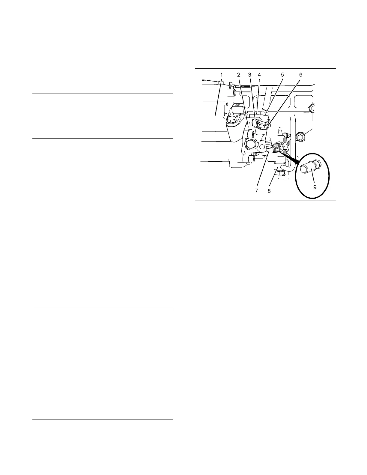
2. Place a suitable container below fuel transfer
pump (2) in orde
r to catch any fuel that might be
spilled.
g01334899
Illustration 7
Typical example
3. Remove plastic tube assembly (7) from fuel
transfer pump (2).
Note: If the tube assembly has quick fit connections,
ensure that the connections are clean before the tube
assembly is plugged.
4. Disconnect plastic tube assembly (5) from the
outlet of fuel transfer pump (2).
Note: If the tube assembly has quick fit connections,
ensure that the connections are clean before the tube
assembly is plugged.
5. Remove connector (6) from fuel transfer pump (2).
Remove the O-ring seal from connector (6).
If necessary, remove connector (9) from fuel
transfer pump (2). Remove the O-ring seal from
the connector (9).
6. Remove tube assembly (8) for the fuel return from
the fuel transfer pump and the cylinder head.
Note: Disconnect the tube assembly at the fuel
transfer pump first in order to drain the fuel from the
cylinder head.
7. Remove tube assembly (4) for the engine oil
supply from fuel injection pump (1).
8. Plug or cap all open ports and tube assemblies
immediately with new plugs or caps.

 Loading...


