144 KENR6932
Disassembly a nd Assembly Section
Installation P
rocedure
Table 65
Required Tools
Tool Part Number Part Description Qty
A
-
T40 Torx Socket 1
B
-
Guide Stud
(M8 by 100 mm)
4
C
21826038
POWERPART
Silicon Rubber Sealant
-
NOTICE
Keep all parts clean from contaminants.
Contaminants may cause rapid wear and shortened
component life.
NOTICE
Care must be taken to ensure that fluids are contained
during performance of inspection, maintenance, test-
ing, adjusting and repair of the product. Be prepared to
collect the fluid with suitable containers before open-
ing any compartment or disassembling any compo-
nent containing fluids.
Dispose of all fl uids according to local regulations and
mandates.
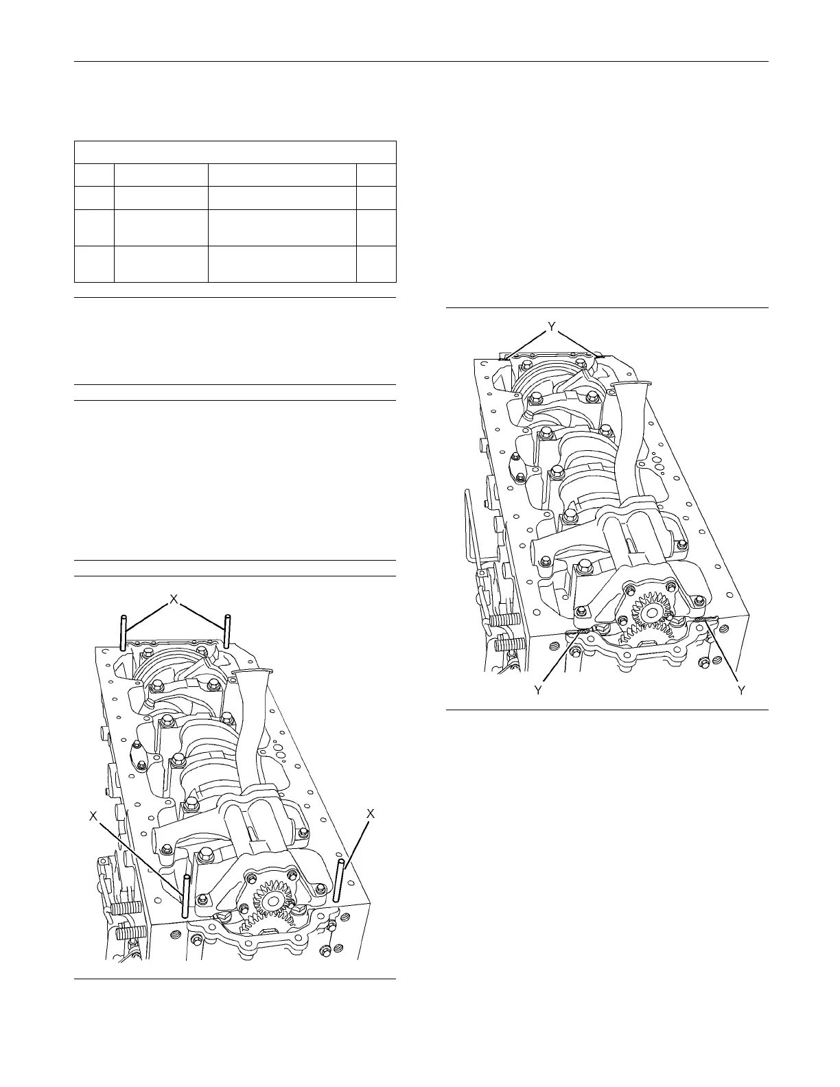
g0134218
6
Illustration 291
Typical exam p le
1. Install Tooling (B) to positions (X) in the cylinder
block.
2. Install the isolating frame to the cylinder block.
Follow Steps 2
.a through 2.f in order to install the
isolating frame.
a. Ensure that th
e joint face of the cylinder block
is clean and free from damage.
b. Ensure that th
e isolating frame is clean and
free from damage. If necessary, replace the
isolating frame.
g013420
58
Illustration 292
Tooling (B) is not shown for c larity.
c. Apply a b
ead of Tooling (C) to positions (Y).

 Loading...


