KENR6932 7
Disassembly and Assembly Section
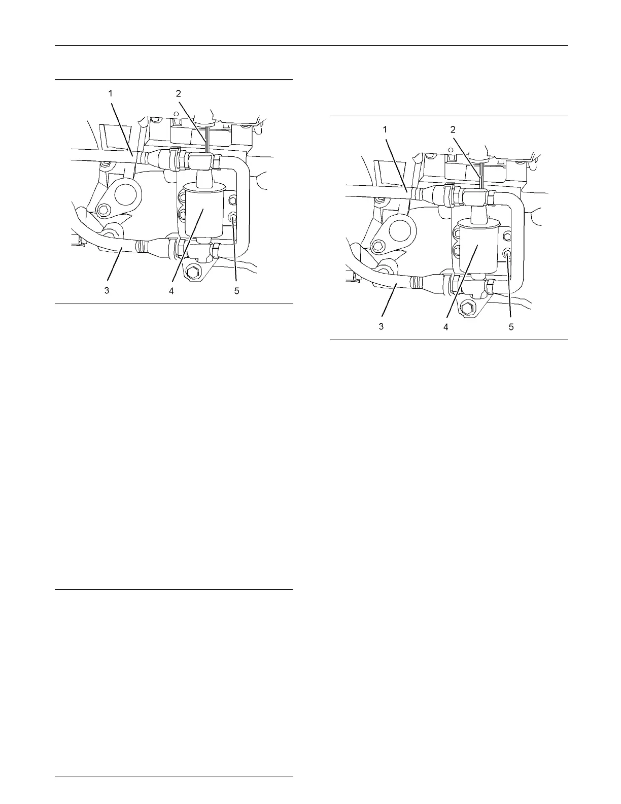
g01334857
Illustration 3
Typical exam p le
2. Isolate the electrical supply.
3. Disconnect harness assembly (2) for electric
priming pump (4).
4. Make a temporary identification mark on plastic
tube assemblies (1) and (3) in order to show the
correct position of the tube assemblies.
5. Disconnect plastic tube assemblies (1) and (3).
Plug the tube assemblies with new plugs. Cap the
ports in fuel priming pump (4) with new caps.
6. Remove bolts (5) from electric priming pump (4).
7. Remove electric priming pump (4) from the
mounting bracket.
Installation Procedure (Electric
Fuel Priming P ump)
NOTICE
Ensure that all adjustments and repairs that are
carried out to the fuel system are performed by
authorised personnel that have the correct train-
ing.
Before begining ANY work on the fuel system, re-
fer to Operation and Maintenance Manual, “Gen-
eral Hazard Information and High Pressure Fuel
Lines” for safety information.
Refer to System Operation, Testing and Adjusting,
“Cleanliness of Fuel System Components” for de-
tailed information on the standards of cleanliness
that must be obs erved during ALL work on the fu-
el system.
1. Ensure that electric priming pump (4) is clean and
free from wear o
r damage. If necessary, replace
the electric priming pump.
g01334857
Illustration 4
Typical example
2. Position electric priming pump (4) on the mounting
bracket. Install bolts (5) to electric priming pump
(4).
3. Tighten bolts (5) to a torque of 9 N·m (79 lb in).
4. Remove the plugs from the plastic tube
assemblies. Remove the caps from the electric
priming pump.
5. Connect plastic tube assemblies (1) and (3) to
electric priming pump (4).
Note: Ensure that the plastic tube assemblies are
installed in the original positions.
6. Connect harness assembly (2) for electric priming
pump (4).
7. Restore the electrical supply.
8. Restore the fuel supply.
9. Prime the fuel system. Refer to Operation and
Maintenance Manual, “Fuel System - Prime”.

 Loading...


