90 KENR6932
Disassembly a nd Assembly Section
Note: Either Tooling (A) can be used. Use the Tooling
that is most sui
table. Care must be taken in order to
ensure that the fuel injection pump timing is not lost
during the removal of the front gear group. Carefully
follow the pro
cedure in order to remove the gear
group.
1. Use Tooling (
A) in order to rotate the crankshaft
so that number one piston is at top dead center
on the compression stroke. Refer to System
Operation, T
esting and Adjusting, “Finding Top
Centre Position for No.1 Piston”.
g01335379
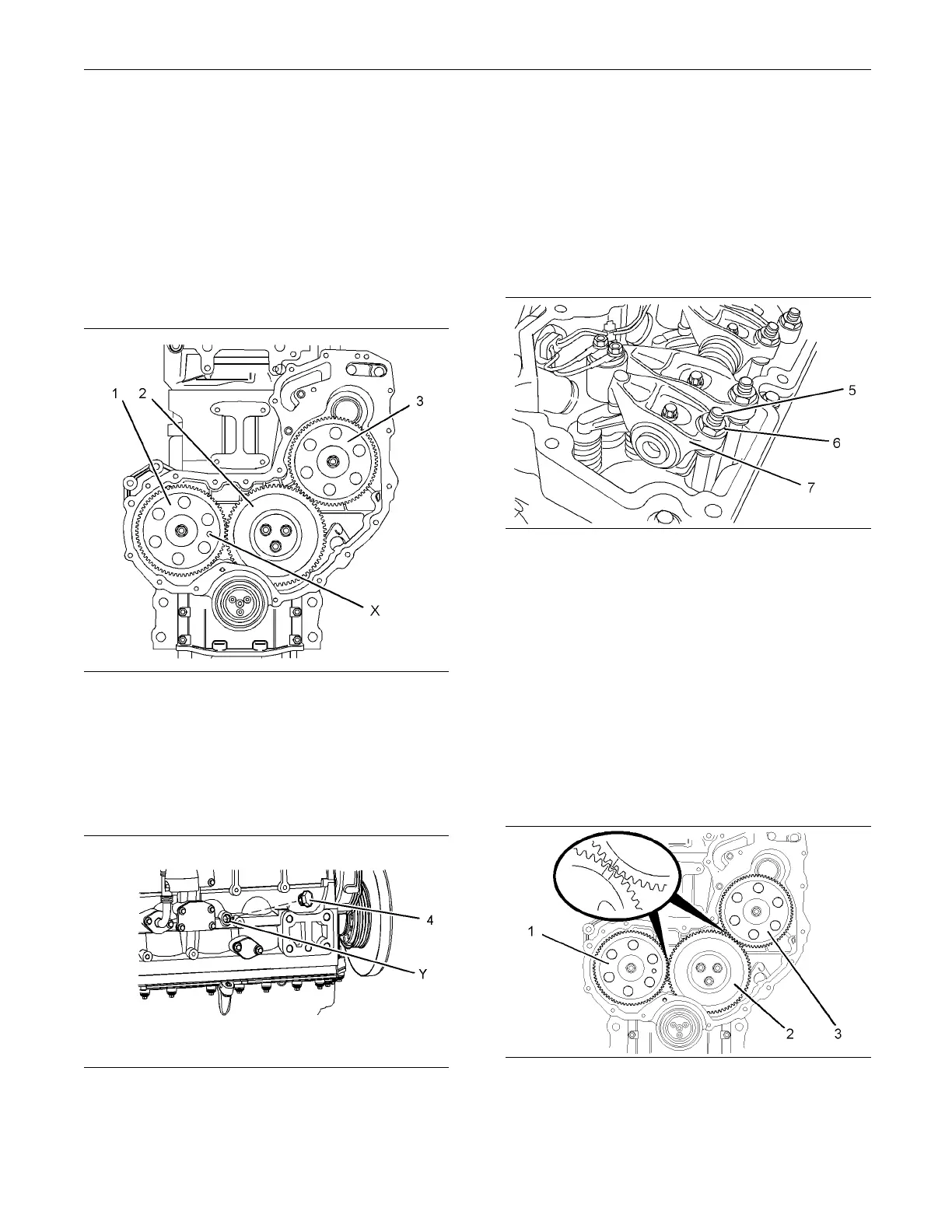
Illustration 158
Typical exam p le
2. Install Tooling (B) through hole (X) in camshaft
gear (1) into the front housing. Use Tooling (B) in
order to lock the camshaft in the correct position.
Refer to System Operation, Testing and Adjusting,
“Finding Top Centre Position for No.1 Piston”.
g01335380
Illustration 159
3. Remove plug (4) from the cylinder block. Install
Tooling (C) int
ohole(Y)inthecylinderblock.
Use Tooling (C) in order to lock the crankshaft in
the correct position. Refer to System Operation,
Te st i ng a n d A d
justing, “Finding Top Centre
Position for No.1 Piston”.
Note: Do not u
se excessive force to install Tooling
(C). Do not use Tooling (C) to hold the crankshaft
during repairs.
g01337898
Illustration 160
4. Loosen nuts (6) on all rocker arms (7). Unscrew
adjusters (5) on all rocker arms (7) until all valves
are fully closed.
Note: Failure to ensure that ALL adjusters are fully
unscrewed can result in contact between the valves
and pistons.
5. Apply sufficient pressure to fuel injection pump
gear (3) in a counterclockwise direction in order
to remove the backlash. Lock the fuel injection
pump in this position. Refer to Disassembly and
Assembly, “Fuel Pump Gear - Remove” for the
correct procedure.
g01335384
Illustration 161
Typical example
6. Mark gears (1), (2) and (3) in order to show
alignment. Refer to Illustration 161.

 Loading...


