X-Series Hyperconverged Nodes Powered by Acuity
Setup & User Guide, v1.0
| 12
DOC-246-GDE-Pivot3 Acuity 2.3 Setup & User Guide-v1.0.docx
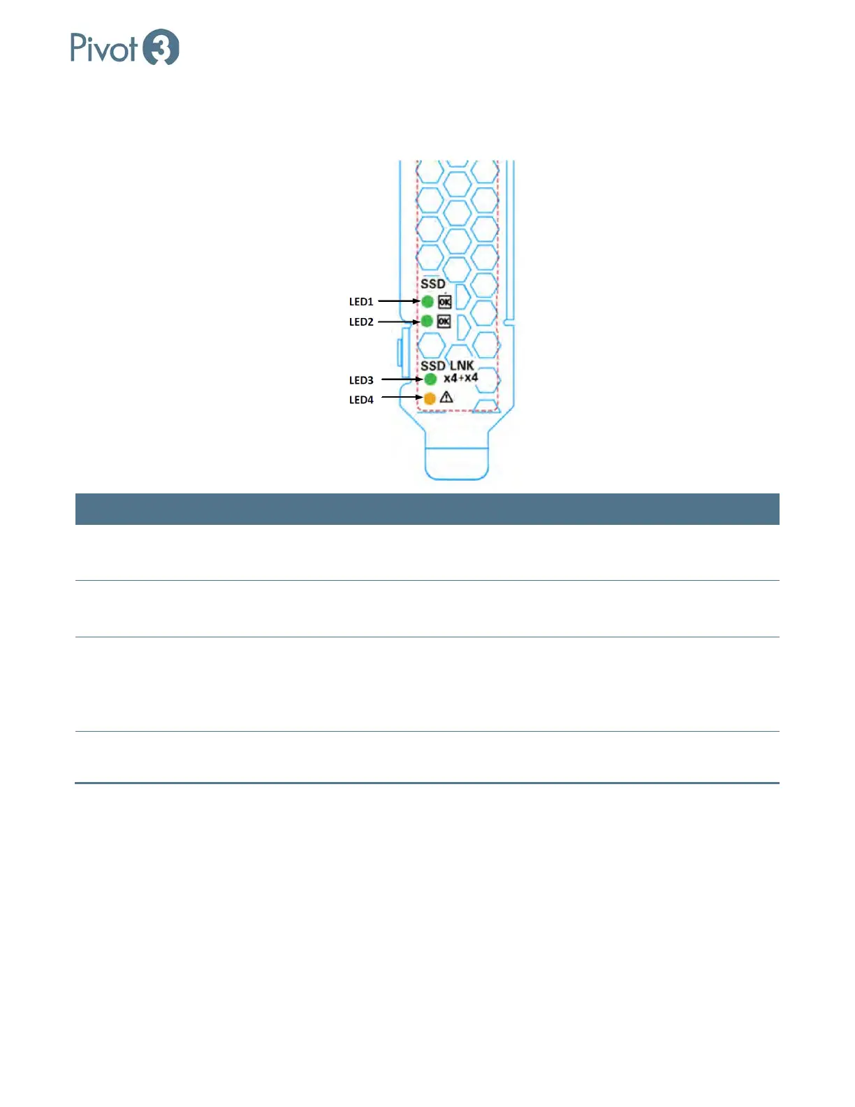
NVMe PCIe Flash LED Status Definitions
On-board LED are provided to indicate the status of the drive.
LED Description Blink Behavior
LED 1 – Activity (Green) Shows I/O activity for ASIC1 –
Blinking, Controlled by Firmware
Solid GREEN: No read/write activity.
Blinking GREEN: read/write activity.
LED2 – Activity (Green)
Shows I/O activity for ASCI2 –
Blinking, controlled by Firmware
Solid GREEN – No read/write activity
Blinking GREEN: read/write activity
LED 3 – Link Behavior Shows link behavior for both
Physical drive controllers
Solid GREEN: Link is established and
GEN3 on all 8 lanes
OFF: Link is established, but Gen 1/2 not
using all 8 lanes.
LED 4 – Fault (Yellow) Fault Solid YELLOW: Critical warning or fault
condition.