CLUTCH
6.13
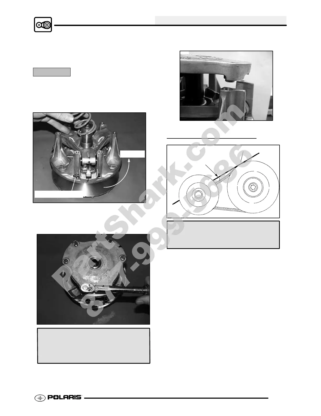
5. Torque spider to specification using the holding
fixture and spider tool. Torque with smooth
motionto avoiddamagetothestationarysheave.
Refer to Page 6.2 for torque specification.
CAUTION:
Be sure the spider spacer washers are fully seatedin
therecessedareainthespider. Any misalignmentwill
alter clutch balance. Inverting the clutch whileinitially
tightening the spider will help position the washers.
Rotation
Nut on trailing side
6. Install shift weights using new lock nuts on the
bolts.
7. Reinstall clutch spring.
Spider Torque:
200 ft. lbs. (276 Nm)
Cover Screw Torque:
90 in. lbs. (10.4 Nm)
8. Reinstall cover, aligning bosses onthe tower and
cover. Torquecover bolts evenlytospecification.
DRIVE BELT TENSION
11/8″ (28.5 mm)
Straight Edge
Belt Deflection (Tension):
11/8″ (2.9 cm) - 1 1/4″ (3.2 cm)
NOTE: Pinchthesheaveslightlytogether withclamp
to prevent the belt from being pushed into the driven
sheave.
1. Place a straight edge on top of the belt between
drive and driven clutch.
2. Pushdownondrivebeltuntilitislightlytensioned.
3. Measure belt deflection as shown in photo.
NOTE: If belt deflection is out of specification, adjust
by removing or adding shims between the driven
clutch sheaves.
G Remove shims to decrease belt
deflection
G Add shimstoincreasebelt deflection
See DRIVEN CLUTCH
DISASSEMBLY/INSPECTION, Pages 6.19 - 6.20.
PartShark.com
877-999-5686
 Loading...