MAINTENANCE
2.33
Shock Spanner Wrench
(PN 2870872)
CONTROLS
Check contr ols for proper operat ion, pos itioning
and adjus tment .
G Brake control and switch must be
positioned to allow brake lever to
travel throughout entire range
without contacting switch body.
WHEELS
Inspectallwheelsfor runoutordamage. Checkwheel
nuts and ensuretheyaretight. Donotovertightenthe
wheel nuts.
WHEEL, HUB, AND SPINDLE
TORQUE T
ABLE
Item Specification
Front Wheel Nuts 27 Ft. lbs. (37 Nm)
Rear Wheel Nuts 50 Ft. Lbs. (68 Nm)
Front Spindle Nut 40 Ft Lbs. (54Nm)
Rear Hub Retaining Nut 80 Ft. Lbs. (108 Nm)
WHEEL REMOVAL FRONT OR
REAR
1. Stop the engine, place the transmission in gear
and lock the parking brake.
2. Loosen the wheel nuts slightly.
3. Elevate the side of the vehicle by placing a
suitable stand under the footrest frame.
4. Remove the wheel nuts and remove the wheel.
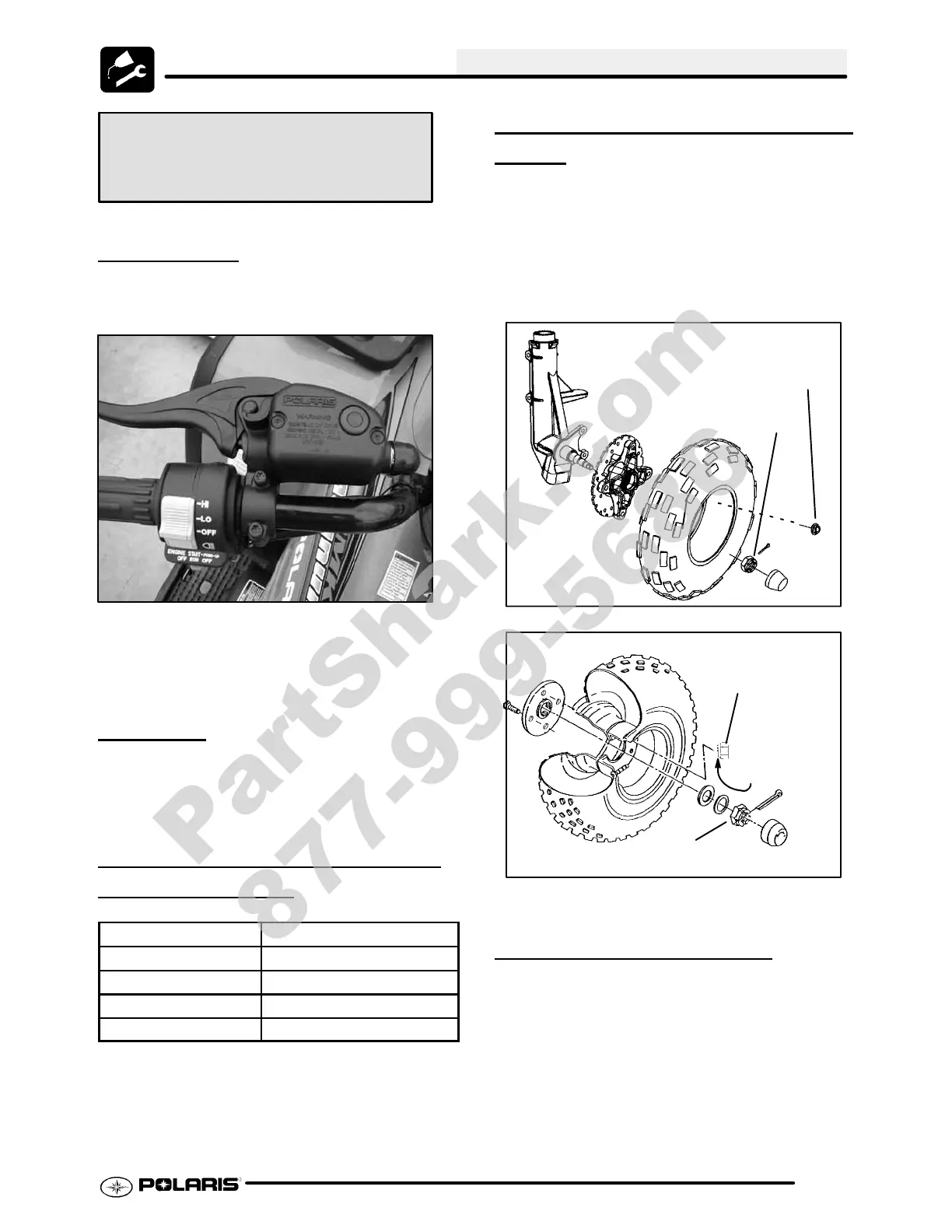
Front Wheel Nuts (4)
27 ft. lbs. (37 Nm)
Front Spindle Nut
40 ft. lbs. (54 Nm)
Front Wheel
Rear Wheel
Rear Wheel Nuts (4)
50 ft. lbs. (68 Nm)
Rear Hub Nut
80 ft. lbs. (108 Nm)
Taper end faces
wheel for install.
WHEEL INSTALLATION
1. With the transmission in gear and the parking
brake locked, place the wheel in the correct
positiononthewheelhub. Be surethevalvestem
is toward the outside and rotation arrows on the
tire point toward forward rotation.
2. Attach the wheel nuts and finger tighten them.
NOTE: Install the tapered end of the rear wheel nut
goes into the taper of the wheel. See illustration
above.
PartShark.com
877-999-5686
 Loading...