ENGINE
3.33
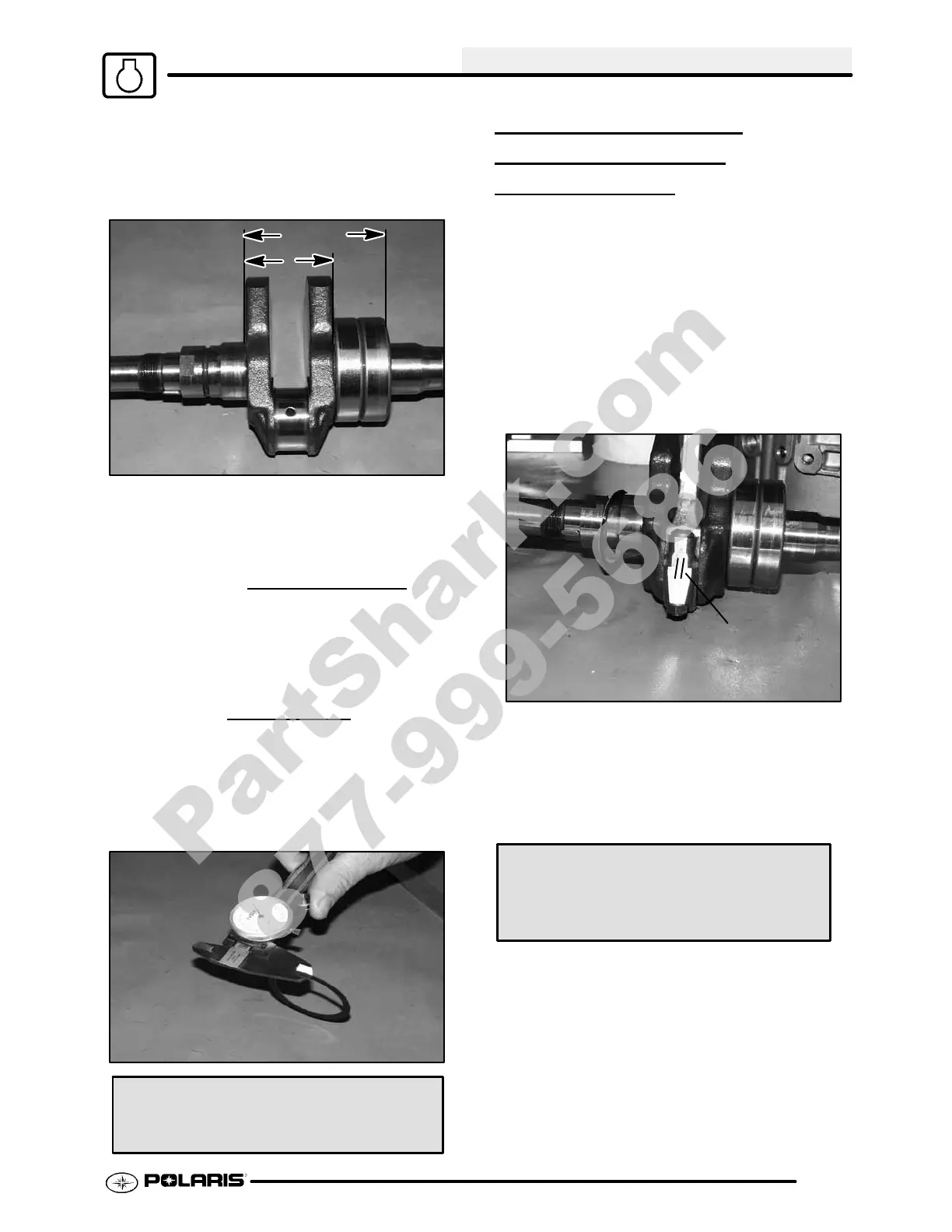
4. Measure the width of the crankshaft at the
bearingseatsor,ifPTObearingsareinstalled,the
width from MAG side bearing seat to the outside
raceofthePT Obearingswithamicrometerordial
caliper and record.
NOTE: If PTO bearings are not installed,
measure the width of the bearings and add to
crankshaft width.
Crankshaft Width
5. Subtract the Crankshaft Width measured in Step
4 from the Total Case Width recorded in Step 3,
and record below.
Total End Play
6. Subtract the thickness of the existing shim from
theresultof Step5todetermineif a differentshim
is required. The result must be within the
specified range listed below. Increase or
decreaseshimthickness as requiredto bringend
play within range.
Crankshaft End Play:
008″-.016″ (.02-.04 cm)
ENGINE ASSEMBLY/
CONNECTING
ROD
INSTALLA
TION
1. Clean all oil off connecting rod, connecting rod
cap and bearing inserts.
2. Install bearing inserts onto connecting rod and
cap.
NOTE: First, install bearing tab into groove, then
press the rest of the bearing into place.
3. Apply assembly lube onto the connecting rod
bearings and crank pin.
4. Install rod and cap onto the crankshaft. Ensure
that I.D. marks are aligned.
Marks
NOTE: Procedure during disassembly called for
markingofconnectingrodandcap. Ensurethat each
part is installed in its original location by noting the
marks placed on the parts during disassembly.
5. Tighten rod cap nuts to 1/2 torque specification,
then full torque.
Rod Nut Torque:
29-33 ft. lbs. (39-45 Nm)
6. Verify that the connecting rod is free to rotate on
the crankshaft journal.
PartShark.com
877-999-5686
 Loading...