CLUTCH
6.20
7. Remove moveable sheave and note the number
of spacer washers. One spacer must remain
between the sheaves when adjusting belt
deflection.
Inspect bushings for wear
Moveable Sheave Bushing Inspection:
Replace the bushing if more brass than
Teflont is visible on the bushing. Re-
fer to bushing replacement in this
chapter.
8. Inspect the Teflont coating on the moveable
sheave bushing.
9. Inspect driven clutch faces for wear or damage.
10. Clean and inspect splines on helix and
transmission input shaft.
11. Lube splines with a light film of grease. Do not
lubricate the bushings!
DRIVEN CLUTCH ASSEMBLY
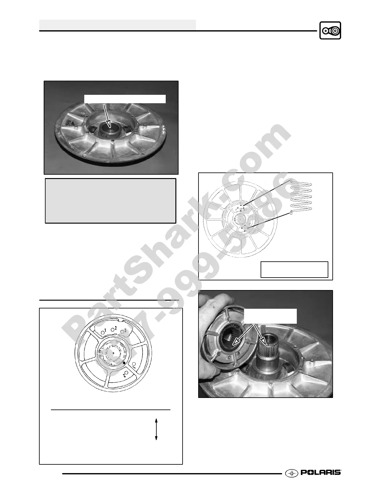
Moveable Spring
Example: Helix Sheave Tension
2 -- 1 Heavy
Spring/ 2 -- 2
Position 1 -- 1
2--3
1--2
1--3 Soft
Refer to General Information Chapter 1 for driv-
en clutch spring color and production setting.
1. Install moveable sheave with spacer washers.
Important: At least one spacer washer must be
installed. Teflont bushings are self-lubricating.
Do not apply oil or grease to the bushings.
2. Install spring, inserting spring tabintoproperhole
in moveable sheave.
3. Insert spring tab into proper hole in helix. See
specifications Chapter 1 or Illustration 2 below.
The driven clutch, helix/moveable assembly has
several different spring locations which affect clutch
shifting and RPMs. The greatest amount of spring
tension will raise engine RPMs during clutch upshift
and allow quicker backshift or downshift when pulling
or negotiatinga hill, for example. Theleast amount of
tension will create a slower downshift and a harder
upshift.
Driven Clutch
Driven Spring
T railboss 330 Driven
Spring Placement: 2--2
Ill. 2
Align boss spline
to install helix
4. Line up boss spline and push helix down until it
engages the splines 1/2″ to 3/4″.
PartShark.com
877-999-5686
 Loading...