ELECTRICAL
10.10
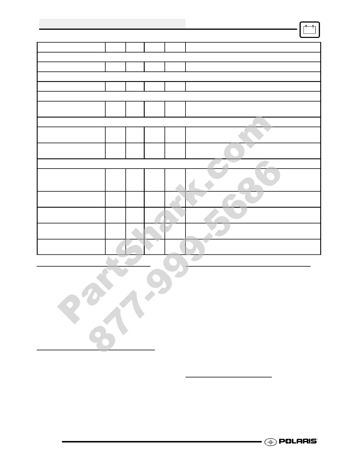
Characteristic MIN TYP MAX UNIT Note
STARTER Output
Current 6 Amp Current capability of the STARTER output
TRANS
Neutral Voltage 4.5 -- 16 Vdc
BRAKE On
Input Voltage 2 14 16 Vdc Voltage on BRAKE input to activate the STARTER
output
REVERSE POLARITY PROTECTION
Battery Reverse Current 1.8 2 mA Max reverse leakage current when connected in
reverse
Reverse Bias Voltage -- 55 Vdc Absolute maximum reverse voltage before device
breakdown
TEMPERATURE CONTROLLER
Open Thermistor
Resistance
50k ohm Above this resistance is assumed to be an open
thermistor , causing the FAN and HOT indicator to
activate
Fan OFF Resistance 3362 3466 3570 ohm Thermistor resistance above this value will turn off
the fan
Fan ON Resistance 2426 2519 2612 ohm Thermistor resistance below this value will turn on
the fan
Engine Temperature In-
dicator ON Resistance
1534 1607 1680 ohm Thermistor resistance below this value will cause
the HOT indicator output to pull low
Engine Temperature In-
dicator OFF Resistance
1534 1607 1680 ohm Thermistor resistances above this value will not
activate the HOT inidicator output
’HOT’ LIGHT OPERATION
With the ignition switch (and engine stop switch) “ON”,
power is delivered to the hot light via the Red/White
wire. The Blue/White wire (ground) out of the light
socket is connected to the PDM. If engine coolant
reaches the specified temperature, the thermistor
sends a signal to the PDM, which completes the
ground path for the light. An open thermistor will
cause the engine hot indicator to light and cause the
fan motor to come on.
HOT LIGHT CIRCUIT TEST
1. Disconnect the thermistor.
2. T urn key and auxiliary switch to “ON” position.
The hot lamp (and fan) should come on. Check
the bulb and related wiring if the lamp does not
illuminate. Check PDM for proper operation.
FANOPERATION/TESTING
Power to the fan is supplied via the PDM when the
ignition key and auxiliary shut--off switch are ON.
When the thermistor reaches the specified
resistance,thesignalis readby the PDM, whichturns
onpower toOrange/Blk wire. Thegroundpathfor the
fan motor is through the Brown wire in the harness.
CAUTION: Keep hands away fromfanblades during
this procedure. Serious personal injury could result.
NOTE: The fan switch may not function or operation
may be delayed if oil level is low or if air is trapped in the
system. Be sure syste m is full and purged of air . Refer
to Maintenance Chapter 2.
FAN BYPASS TEST
1. Disconnect the harness from the thermistor .
2. T urn ignition key (and engine stop switch) “ON”.
The fan (and hot indicator) should turn on.
3. If thefandoes notrunorrunsslowlycheckthefan
motor wiring, ground, motor condition (refer to
Fan Motor Testingthissection) and PDM. Repair
or replace as necessary.
PartShark.com
877-999-5686
 Loading...