11.32
9925724 R01 - 2014-2015 RZR XP 1000 / RZR XP4 1000 Service Manual
© Copyright 2014 Polaris Industries Inc.
Charging System Stator (Alternator) Tests
Three tests can be performed using a multi-meter to
determine the condition of the stator (alternator).
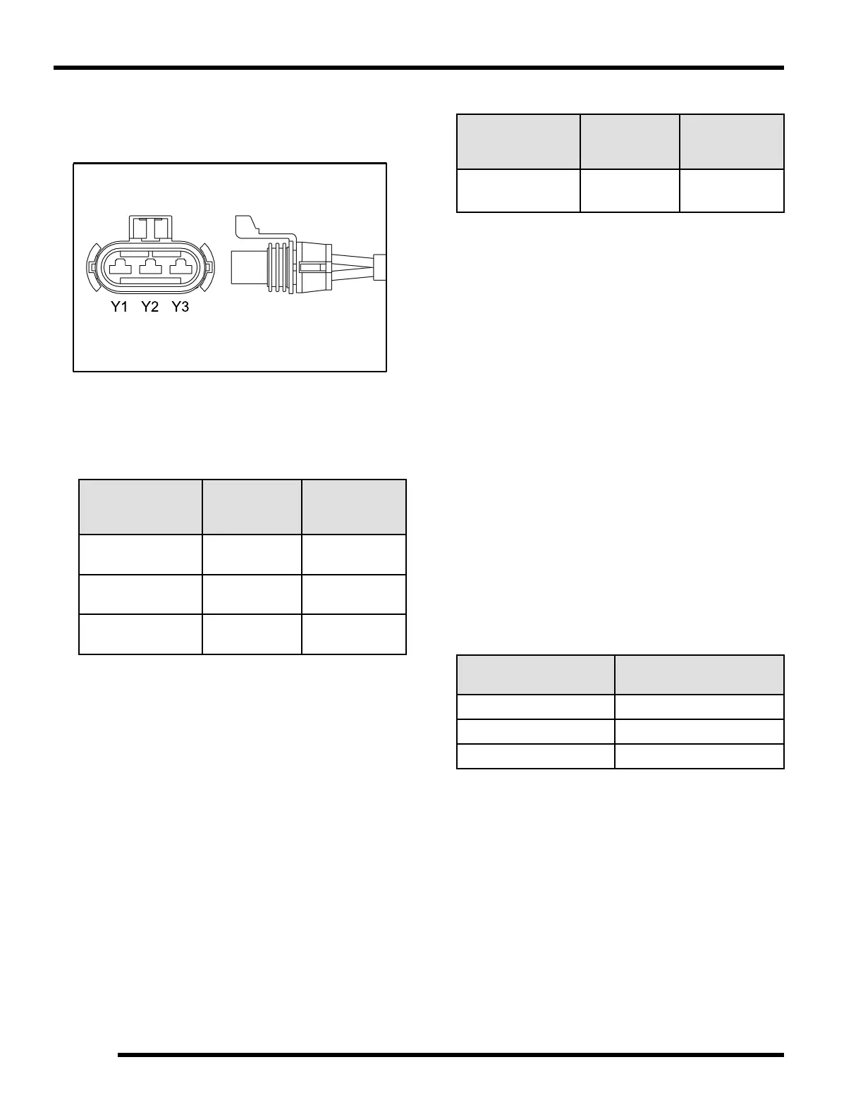
TEST 1: Resistance Value of Each Stator Leg
1. Measure the resistance value of each of the three
stator legs: Y1 to Y2, Y1 to Y3, and Y2 to Y3. Each
test should measure: 0.07 - 0.13 Ω
TEST
CONNECT
METER
LEADS TO:
OHMS
READING
Battery Charge
Coil
Y1 to Y2 0.07 - 0.13 Ω
Battery Charge
Coil
Y1 to Y3 0.07 - 0.13 Ω
Battery Charge
Coil
Y2 to Y3
0.07 - 0.13 Ω
NOTE: If there are any significant variations in
ohm readings between the three legs it is an
indication that one of the stator legs may be
weak or failed.
TEST 2: Resistance Value of Each Stator Leg to
Ground
2. Measure the resistance value of each of the stator
legs to ground: Y1 to Ground, Y2 to Ground, Y3 to
Ground.
3. Each test should measure: Open Line (OL)
TEST
CONNECT
METER
LEADS TO:
OHMS
READING
Battery Charge
Coil
Y1, Y2, or Y3
to Ground
Open Line
(Infinity)
NOTE: Any measurement other than Infinity
(open) will indicate a failed or shorted stator leg.
TEST 3: Measure AC Voltage Output of Each
Stator Leg at Charging RPM
4. Set the selector dial to measure AC Voltage.
5. Start the engine and let it idle.
6. While holding the engine at a specified RPM,
separately measure the voltage across each ‘leg’ of
the stator by connecting the meter leads to the wires
leading from the alternator (Y1 to Y2, Y1 to Y3, Y2 to
Y3).
7. Refer to the following table for approximate AC
Voltage readings according to RPM. Test each leg at
the specified RPM in the table.
8. Example: The alternator current output reading
should be approximately 21 VAC at 1300 RPM
between each ‘leg’.
NOTE: If one or more of the stator leg output AC
voltage varies significantly from the specified
value, the stator may need to be replaced.
RPM READING
AC VOLTAGE (VAC)
READING
1300 21 VAC ± 25%
3000 47 VAC ± 25%
5000 79 VAC ± 25%
ELECTRICAL
 Loading...