Byte 1 +24 V
input
Byte 2 +24 V
input
Byte 3 +24 V
input
pin 1 1. in bit pin 1 9. in bit pin 1 17. in bit
pin 2 2. in bit pin 2 10. in bit pin 2 18. in bit
pin 3 3. in bit pin 3 11. in bit pin 3 19. in bit
pin 4 4. in bit pin 4 12. in bit pin 4 20. in bit
pin 5 5. in bit pin 5 13. in bit pin 5 21. in bit
pin 6 6. in bit pin 6 14. in bit pin 6 22. in bit
pin 7 7. in bit pin 7 15. in bit pin 7 23. in bit
pin 8 8. in bit pin 8 16. in bit pin 8 24. in bit
The input LEDs are located in the input path and therefore show
the real state of the 24V inputs
n a HIGH input signal causes the corresponding LED to turn ON
n a LOW input signal causes the corresponding LED to turn OFF
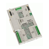
Fig. 30: PAMIO 2416 inputs status LEDs
Pin Assignment
Input Status LEDs
PA 8000 PAMIO
PAMIO Components
12.01.2017 | 55
 Loading...