11.3.2 Direct Connections to CT with Separate Neutrals
This set of instructions is applicable when all active CTs do not share a common neutral and/or
ground.
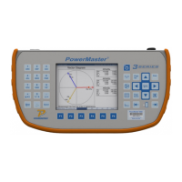
STEP 1
Insert direct current probes
into test switch.
STEP 2
Verify Length is set to 0 and
“Simultaneous Measurement”
is NOT selected. Press F6 to
continue.
STEP 3
Test will pause waiting for
user input
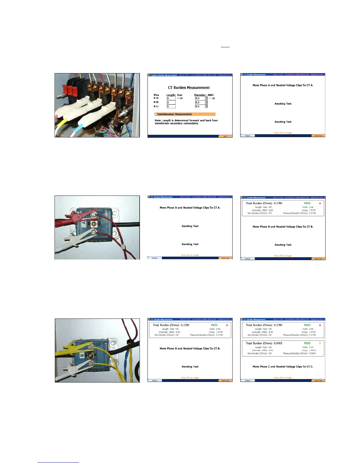
STEP 4
Connect the red (+) and white
(-) voltage cable connections
to the CT secondary for A
phase
STEP 5
Press F6 to test A phase CT
STEP 6
View results for A phase CT
STEP 7
Connect the yellow (+) and
move the white (-) voltage
cable connections to the CT
secondary for B phase
STEP 7
Press F6 to test B phase CT
STEP 8
Press F6 to test B phase C
Rev 1.5 101
 Loading...