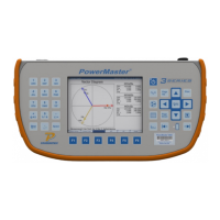
STEP 1
Clamp current probes around
voltage wires at test switch.
Connect voltage leads as
normal.
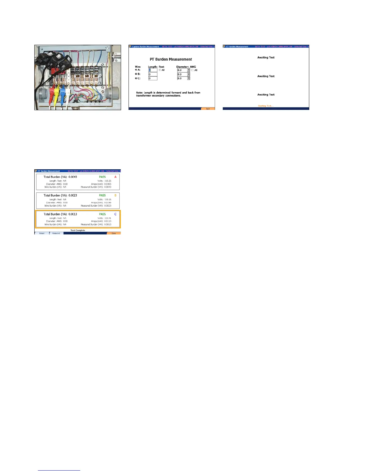
STEP 2
Verify Length is set to 0.
Press F6 to continue.
STEP 3
Test will begin automatically
STEP 4
View results. Press F6 to
save and complete.
11.5.2 Calculated Burden with Connections at Test Switch
This set of instructions is for an application where the PT secondary connections cannot be
accessed. All voltage and current measurements are made at the test switch and resistance (VA)
is calculated based on the wire length and diameter (AWG) connected to the current terminals.
Length is based on the distance from the PT secondary connection to the test switch. AWG can
typically be determined by a notation imprinted on the insulation of the wire (ex. “12 AWG”).
Rev 1.5 110
 Loading...