Verifies connected probes if a problem occurs
Description:
When entering this screen, the PowerMaster
®
performs both a “Probe Scan” (see Section 13.8.2)
and allows the user to verify probe connections. A key is displayed at the left of the screen and
shows what probes are active and required for this test. Color codes are also displayed (A = red,
B = yellow, C = blue, N = gray).
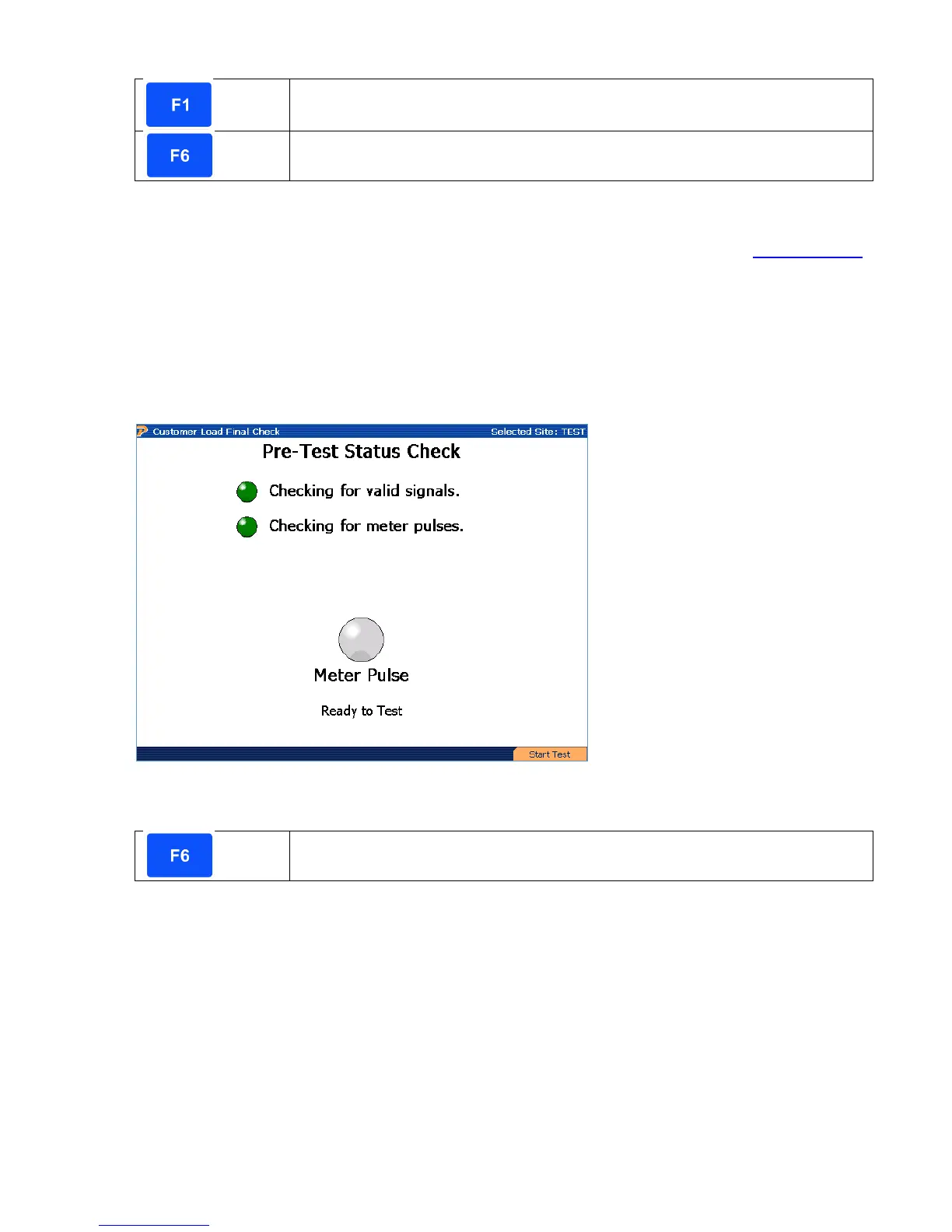
10.1.3 Customer Load Final Check
Functionality:
Description:
When entering this screen, the PowerMaster
®
verifies all current and voltage signals are
reasonable and allows the user to align the meter pulse pickup at this time. When meter pulses
are detected, the signal for “Checking for meter pulses” displays green. Each time a pulse is
detected, the “Meter Pulse” signal will light green and display “Ready to Test.” At this time, the
user presses F6 to continue to the meter test.
When testing a solid state meter, the meter may be required to be in “test mode.” This normally
is done by a toggle switch underneath the meter glass, but in rare cases the user may be
required to change the programming of the meter.
Rev 1.5 77
 Loading...