EasyManuals Logo
Home>PowerMetrix>Measuring Instruments>PowerMaster 3 Series

PowerMetrix PowerMaster 3 Series User Manual

PowerMetrix PowerMaster 3 Series
157 pages
To Next Page IconTo Next Page
To Previous Page IconTo Previous Page
Page #103 background imageLoading...
Page #103 background image
STEP 4
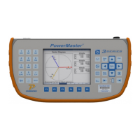
View results. Press F6 to
save and complete.
11.3.4 Calculated Burden with Connections at Test Switch and Separate
Neutrals
This set of instructions is similar to Section 11.2.3, but the user must move the white voltage clip
to the Neutral phase associated with the CT under test.
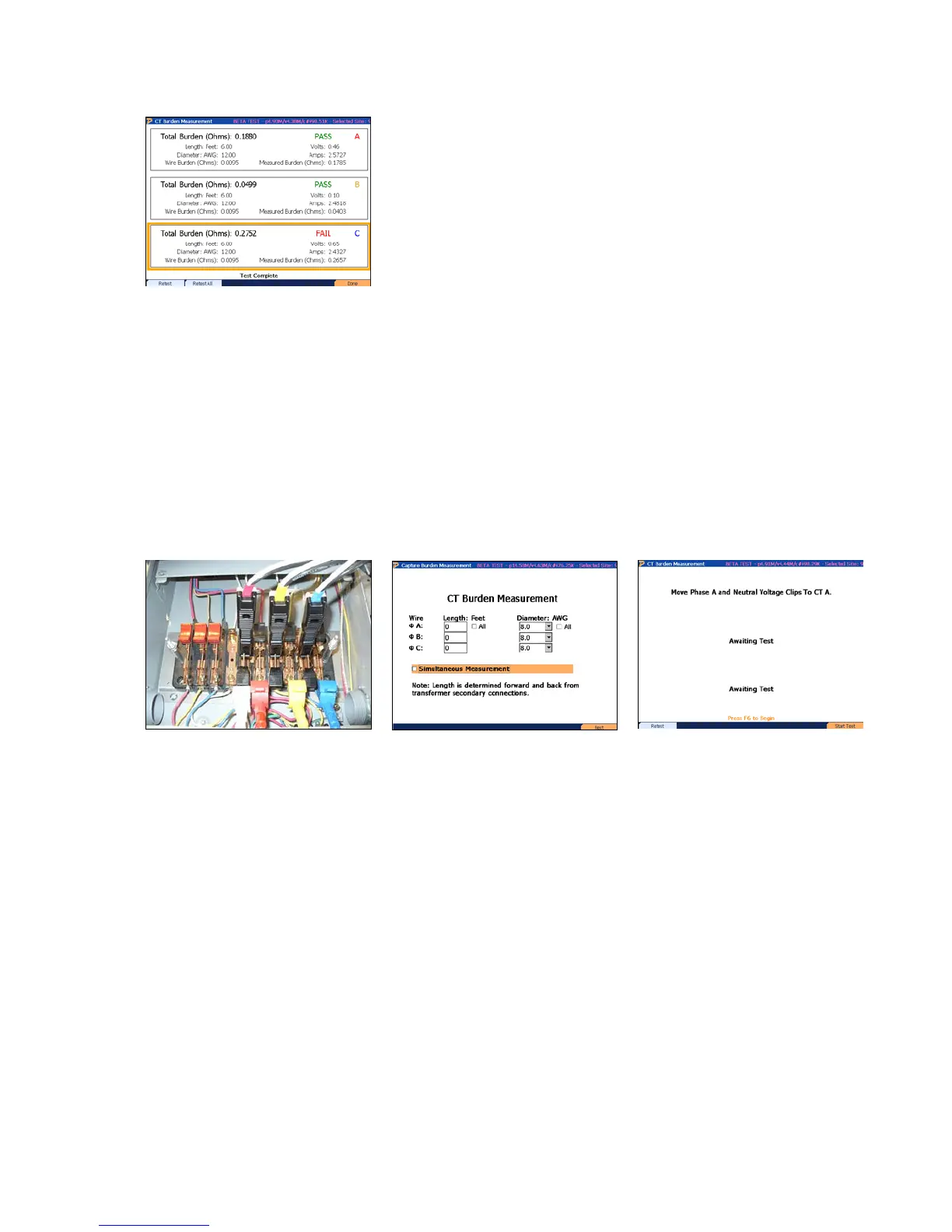
STEP 1
Insert direct current probes
into test switch. Move the
voltage leads to the bottom of
the currents. Connect the
white lead (Neutral) to the
bottom of A phase current.
STEP 2
Input the total length and
diameter (AWG). Verify
“Simultaneous Measurement”
is NOT selected. Press F6 to
continue.
STEP 3
Press F6 to test A phase CT
Rev 1.5 103

Table of Contents

Questions and Answers:

Question and Answer IconNeed help?

Do you have a question about the PowerMetrix PowerMaster 3 Series and is the answer not in the manual?

PowerMetrix PowerMaster 3 Series Specifications

General IconGeneral
BrandPowerMetrix
ModelPowerMaster 3 Series
CategoryMeasuring Instruments
LanguageEnglish