11.3 CT Burden Measurement
Description:
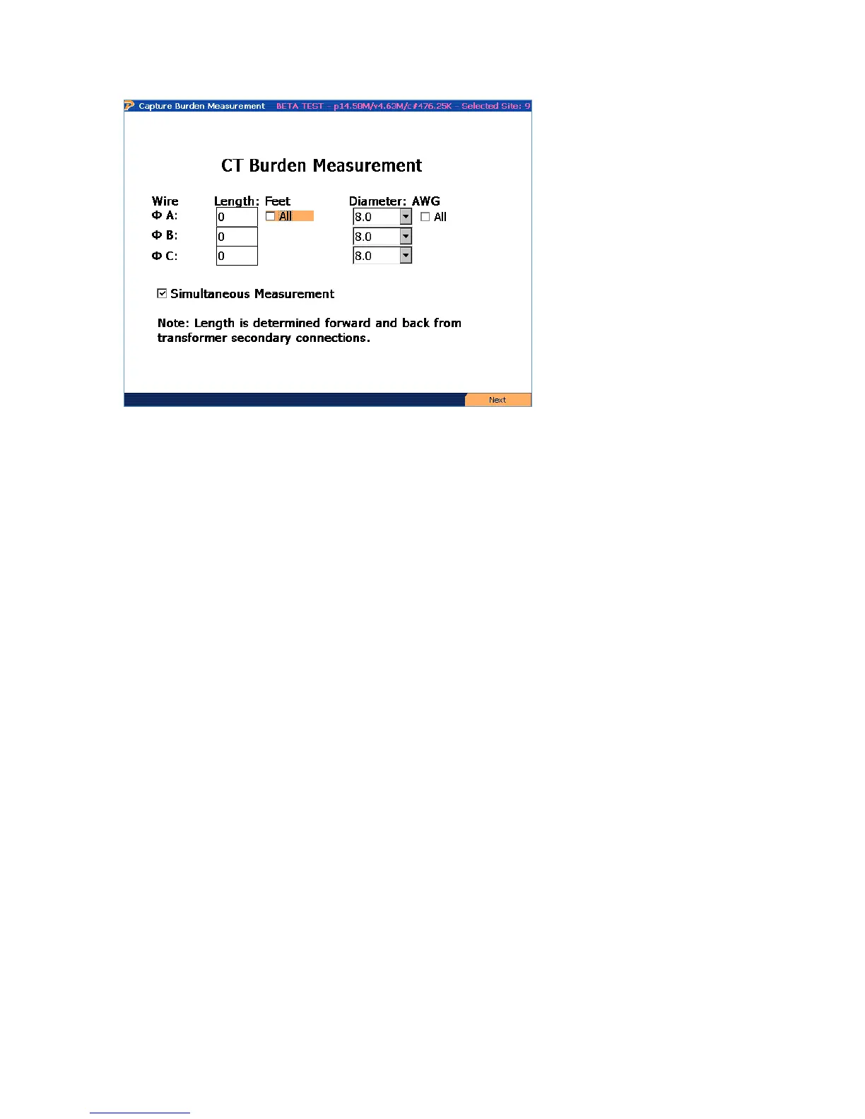
This application allows the user to perform an in service burden measurement of the CT circuit.
There are four different methods to measure the burden in the system using the PowerMaster
®
:
1. Direct Connections to CT with Common Neutral Phase
2. Direct Connections to CT with Separate Neutrals
3. Calculated Burden with Connections to Test Switch and Common Neutral Phase
4. Calculated Burden with Connections to Test Switch and Separate Neutrals
For each method, the PowerMaster
®
measures the entire resistance in the circuit for each CT. If
a CT is selected in the Site Editor, the PowerMaster
®
will display a PASS or FAIL message on the
screen based on burden rating (Ohms). If a FAIL message is displayed, this means that the
measured resistance in the circuit exceeds the manufacturer’s stated burden rating. If resistance
increases enough to over burden the CT, less secondary current is produced. This scenario
results in a billing error even though the meter is functioning correctly.
Once an error is detected by the PowerMaster
®
, the technician should follow methods on
decreasing the actual burden. This normally consists of tightening down connections at the test
switch and/or CT secondary terminals. If a problem remains, the technician may consider
replacing the CT with a higher burden rating to validate resistance is within specification.
Rev 1.5 99
 Loading...