Description:
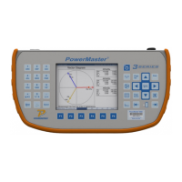
The vector diagram is arguably the best tool for site analysis. In one screen, the PowerMaster
®
displays the phase relationship between the current and voltages. The PowerMaster
®
considers
this relationship to be the “power pair” where all power is calculated. The amplitude of the
voltage and current (i.e. length of the displayed line) is proportionate to the current and voltage
readings. In other words, as the current increases the line will increase in length. The phase
angle is displayed to show the relationship in time (by convention it is displayed in degrees)
according to the way the service transformers are wired. In the USA, Van or Vab is always
displayed at the 0° line (i.e. 3 o’clock position). In Canada, service types typically plot Ean at
330° and Eab at 270°.
The user is allowed to change the “power pair” when primary probes are detected (voltage and/or
current). For secondary currents, the vector displays “SVan” to signify the secondary current for
A voltage in reference to Neutral. Similarly, the secondary currents are labeled “SIa” to signify
the secondary current for A phase. If primary probes are detected, the user can press F4 to
switch the “power pair” to view the relationship between the secondary voltages (SVan) and the
primary currents (PIa). The user can press the F4 key again to view the relationship between the
primary voltages (PVan) and the primary currents (PIa) as well. Power will be calculated
accordingly.
Leading or lagging power factor is also displayed here. As the current vector shifts to the right of
the voltage vector, the power factor is considered to be “lagging” and termed as an inductive load.
This is normal in most metering installations. As the current vector shifts to the left of the voltage
vector, the power factor is considered to be “leading” and termed as a capacitive load. A leading
power factor is not as common in metering, but is normally seen when capacitor banks are used
in service installations when no load is present.
Rotation (“ROT”) is displayed in the System (SYS) box to signify the rotation of the service
transformers (ABC or CBA). The “SYS” values are the averages of the voltage, current, and
power factor for all active phases.
Rev 1.5 61
 Loading...