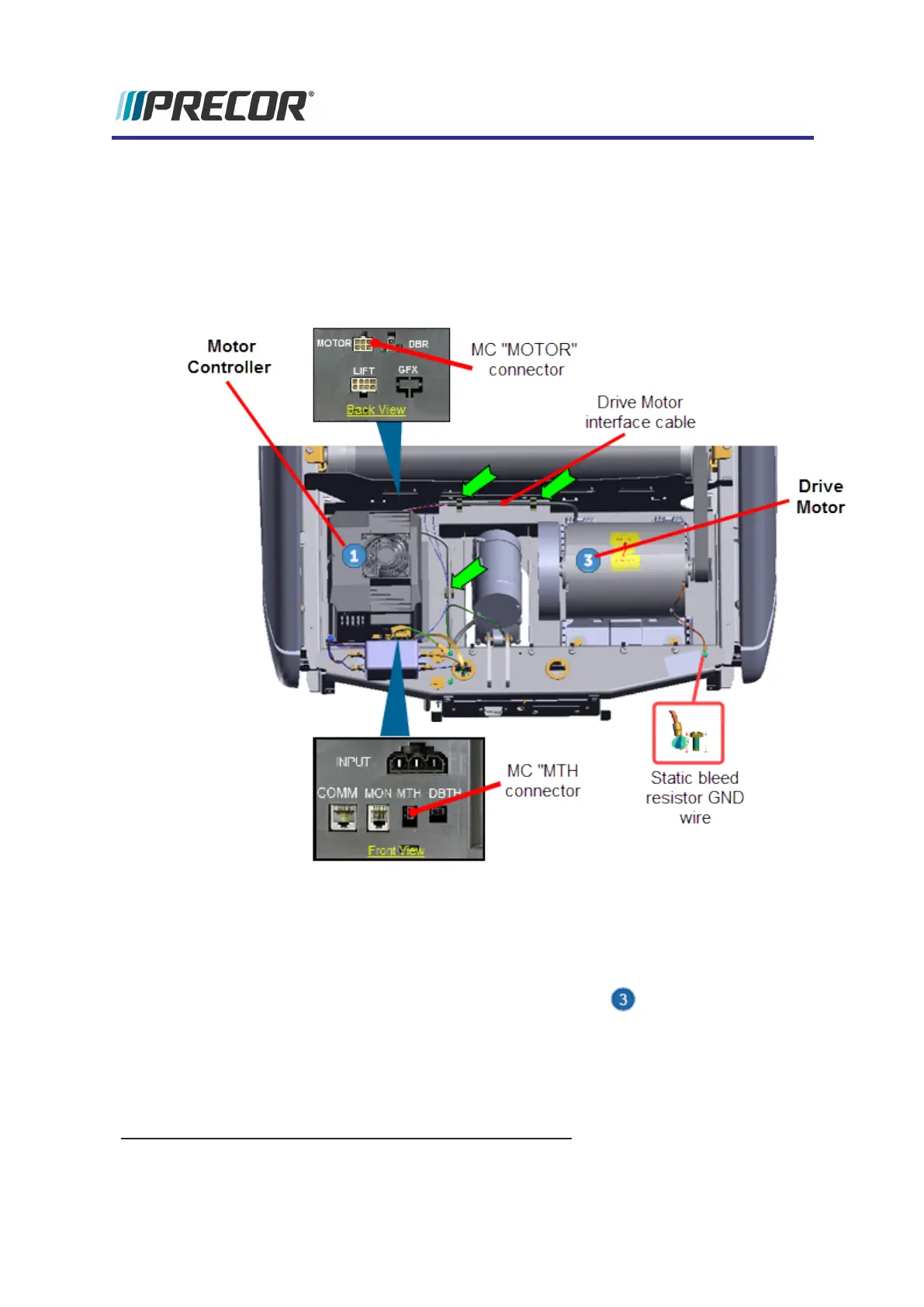
3. Disconnect the Motor Controller "MTH" and "MOTOR" electrical connections:
a. Remove the MC
1
base from the mounting fasteners to allow connector access,
see "Motor Controller (MC) Replacement" on page84.
b. Disconnect the MC "MTH" and "MOTOR" interface cable connectors, see "Motor
Controller (MC) Replacement" on page84.
c. Remove the motor interface cable from the three frame cable clamps.
4. Use a 5/16" socket (or nut driver) to remove the Drive Motor static bleed resistor ground
wire (Orange wire). Retain fastener hardware for installation.
5. Use tape or marker to make a motor base position reference mark. This reference mark
will be used to help position the replacement motor installation position.
6.
Remove Drive Belt tension by loosening the four Drive Motor 1/2" hex head fasten-
ers. Remove the Drive Belt by walking the belt off the Roller pulley and then the motor
pulley.
1
Motor Controller Module
Experience Series 700 Line Treadmills
102
5 Replacement Procedures
Drive Motor Replacement