ASL PCA Replacement
About
This procedure provides instruction to replace the ASL
1
PCA board.
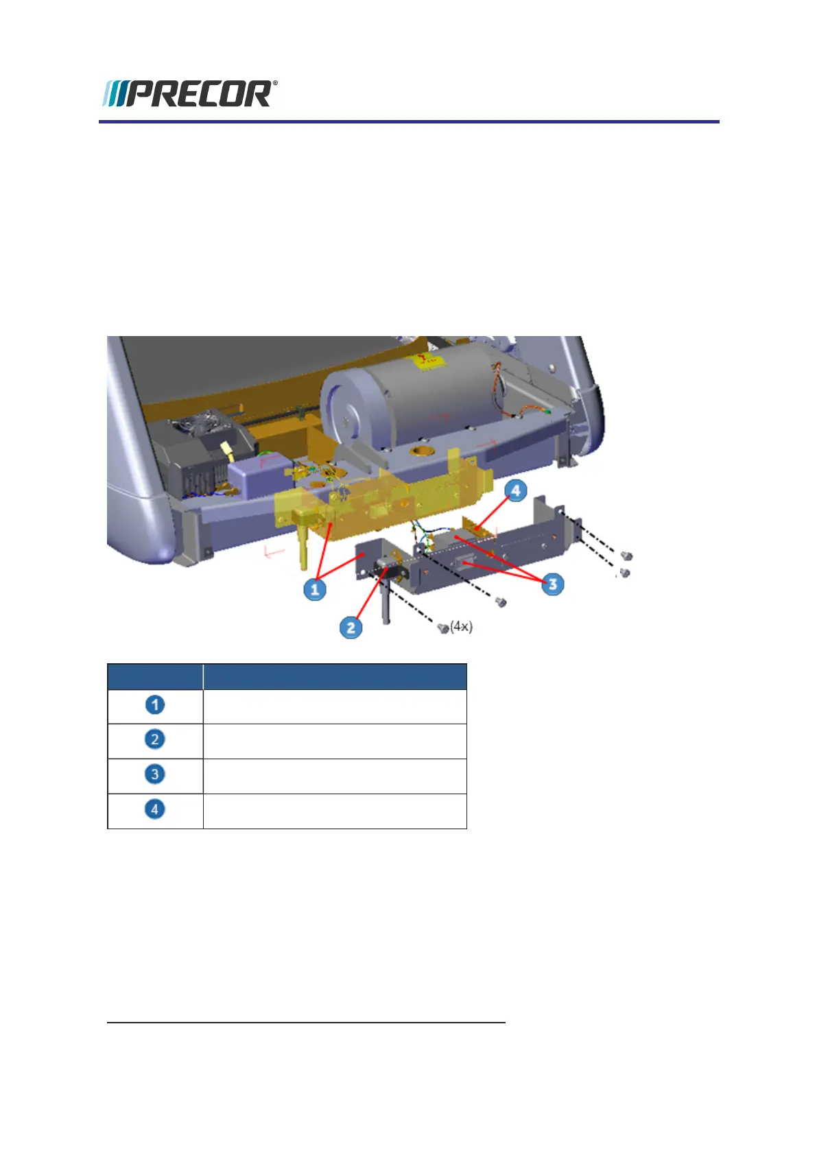
The Power Entry Assembly located in the front of the treadmill under the frame weldment
cross member contains the Power Cord Inlet Assembly, the ON/OFF SW Circuit Breaker, and
the ASLPCA board. The Power Entry Assembly Bracket must be removed to access these
components.
ID Description
Power Entry Assembly Bracket
Power Cord Inlet Assy
ON/OFF SW Circuit Breaker
ASL PCA Board
Wire Diagram
Power Entry Assembly wire diagram.
1
Active Status Light: Service and maintenance status light.
Experience Series 700 Line Treadmills
79
5 Replacement Procedures
ASL PCA Replacement