Note:You can alternatively access the lift platform assembly by laying the
treadmill on its side, see "Side lift platform assembly access" on page49 pro-
cedure.
5. Access the service menu (51765761) and select INCLINE TEST. Use the incline con-
trol to set the incline level to 14.
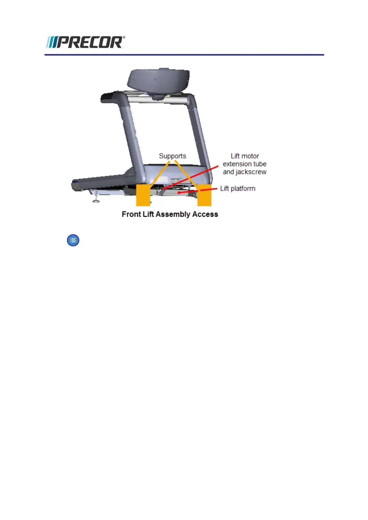
6. Securely and safely place supports (e.g. car jack stands) under the left and right front
corners of the frame weldment.
7. Then lower the incline level in 0.5 increments until the lift platform wheels no longer
touch the floor and the treadmill frame is completely resting on the supports. Keep the
wheels as close to floor as possible without touching the floor making sure all the weight
of the treadmill is carried by the supports. Verify the supports are stable and secure car-
rying the weight of the treadmill.
Remove the lift platform
8. Use tape to mark the location of the extension tube on the jackscrew . Then remove the
lift motor extension tube hitch pin and clevis pin fastener from the lift platform mounting
bracket. Hold the lift platform while removing the clevis pin and carefully rest on the
floor. Keep the extension tube from rotating while disconnecting from the mounting
bracket. Retain fastener hardware for installation.
Experience Series 700 Line Treadmills
132
5 Replacement Procedures
Lift Platform Replacement