EasyManuals Logo

Pulsar ULTRA 5 User Manual

Pulsar ULTRA 5
258 pages
To Next Page IconTo Next Page
To Previous Page IconTo Previous Page
Page #28 background imageLoading...
Page #28 background image
Page 20
Terminal Connections
Power
Ultra 5 can operate from mains AC and automatically from DC or battery
backup in the event of power failure, or can be operated permanently from
DC or batteries.
Transducer
The transducer should be installed, and connected, in accordance with the
installation instructions contained in the Transducer User Guide.
The entire range of, standard dB transducers are certified for use in
hazardous areas and different models, for each, are available for use in Zone
1 or Zone 0.
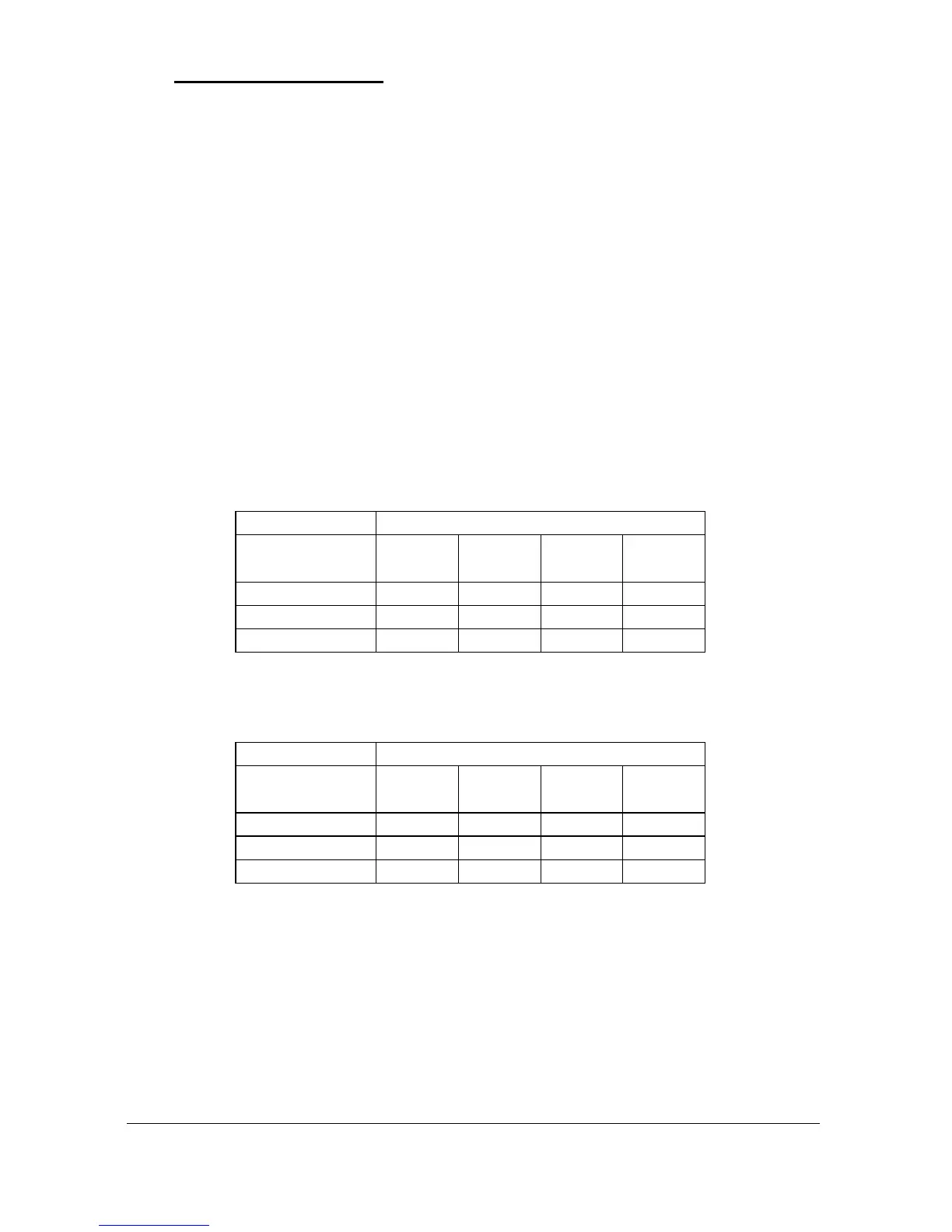
Wire the transducer to the Ultra 5’s transducer terminals, terminal numbers
will depend on the unit type, as follows:
Transducer 1
Terminal Connection Details
Unit Type
Red
Power
White
Signal
Black
0 volts
Green
Screen
Wall Mount
39
40
41
41
Fascia Mount
32
31
30
30
Rack or Panel
c2
c4
c6
c6
Transducer 2
Terminal Connection Details
Unit Type
Red
Power
White
Signal
Black
0 volts
Green
Screen
Wall Mount
42
43
44
44
Fascia Mount
35
34
33
33
Rack or Panel
a6
a8
a10
a10
When using 2-core screened extension cable, the Black and Green wires of
the transducer should be connected to the screen of the extension cable.

Table of Contents

Other manuals for Pulsar ULTRA 5

Questions and Answers:

Question and Answer IconNeed help?

Do you have a question about the Pulsar ULTRA 5 and is the answer not in the manual?

Pulsar ULTRA 5 Specifications

General IconGeneral
BrandPulsar
ModelULTRA 5
CategoryController
LanguageEnglish

Related product manuals