Power sensor tour
R&S
®
NRPxxP
18User Manual 1179.5760.02 ─ 02
4 Power sensor tour
This chapter provides an overview of the available connectors and LEDs of the power
sensor.
NRP18P
SMART SENSOR TECHNOLOGY
1
4
23
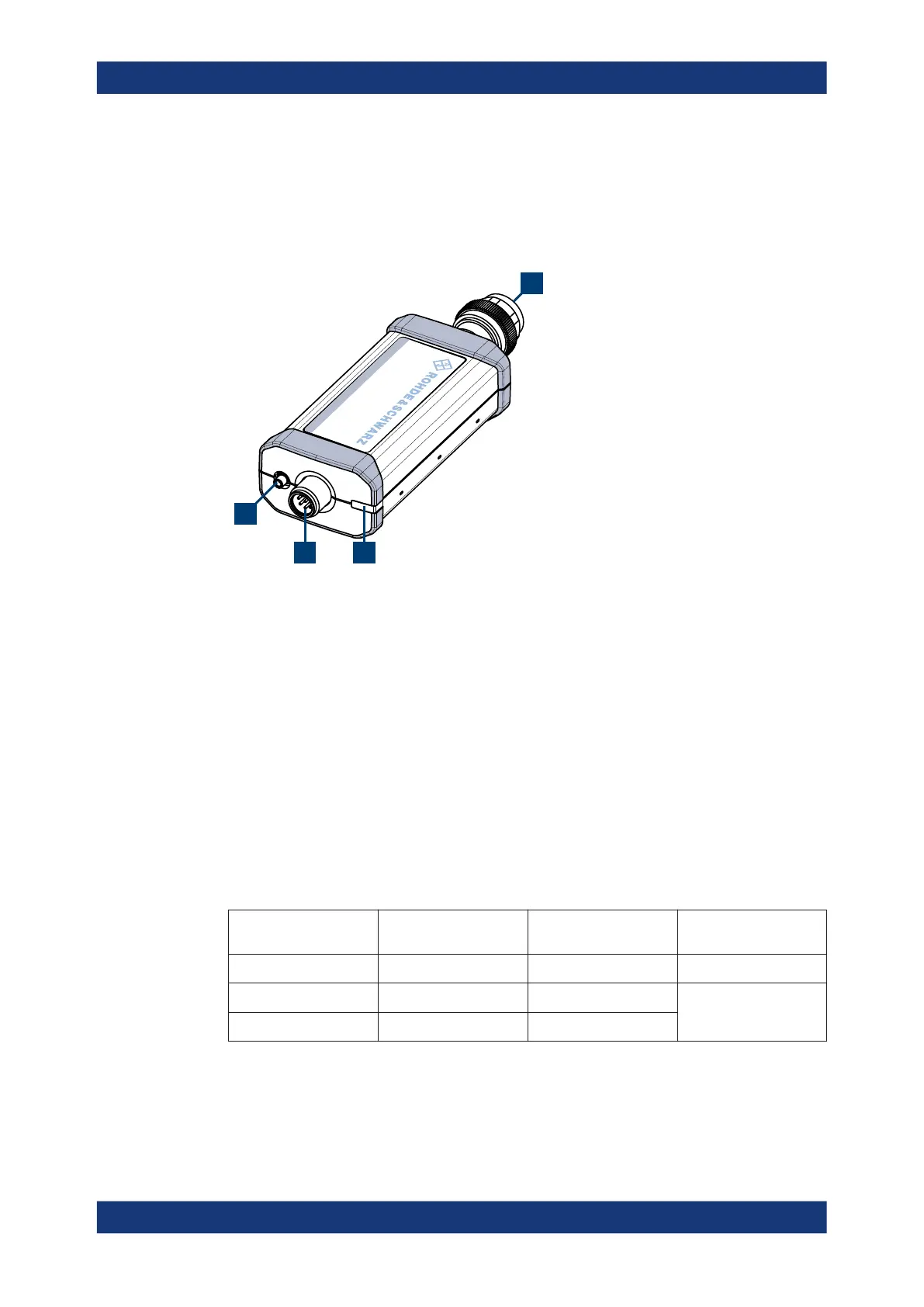
Figure 4-1: R&S
NRPxxP power sensors (example)
1 = RF connector, see Chapter 4.1, "RF connector", on page 18
2 = Status LED, see Chapter 4.2, "Status information", on page 19
3 = Host interface connector, see Chapter 4.3, "Host interface", on page 19
4 = Trigger I/O connector, see Chapter 4.4, "Trigger I/O connector", on page 19
4.1 RF connector
The RF connector is used for connecting the power sensor to a device under test
(DUT) or a signal generator. See Chapter 3.4, "Connecting to a DUT", on page 12.
For maximum measurement accuracy, tighten the RF connector using a torque wrench
with a nominal torque as specified in the following table.
Table 4-1: R&S
NRPxxP RF connector characteristics
Power sensor Male connector Matching female con-
nector
Tightening torque
R&S NRP18P
N N
1.36 Nm (12'' lbs)
R&S NRP40P 2.92 mm 3.50 mm/ 2.92 mm/ SMA
0.90 Nm (8'' lbs)
R&S NRP50P 2.4 mm 2.4 mm/ 1.85 mm
RF connector

 Loading...
