Remote control commands
R&S
®
NRPxxP
54User Manual 1179.5760.02 ─ 02
TRIGger:SENDer:STATe <state>
Available in trace, timeslot modes with TRIGger:SOURce INTernal or BUS.
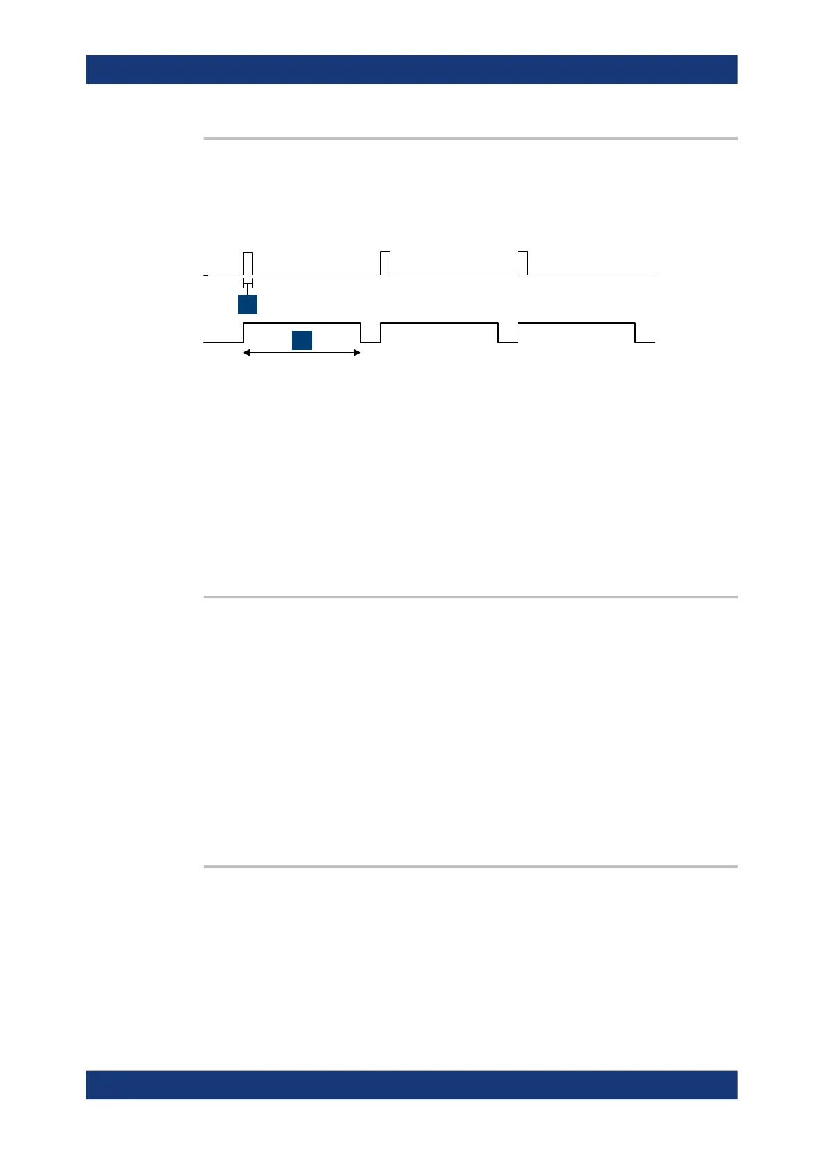
Enables or disables the trigger sender mode of the power sensor. In this state, the
power sensor can output a digital trigger signal in sync with its own trigger event.
1
2
1 = digital trigger signal of 1 μs
2 = one measurement cycle
If enabled, select the output port for the trigger signal using TRIGger:SENDer:PORT.
Typically, the trigger sender uses its internal trigger source. But you can also trigger the
trigger sender externally, because the power sensor has two external trigger connec-
tors. If you trigger the trigger sender externally, use EXTernal1 as external trigger
input port (trigger source) and EXTernal2 as trigger sender output port or vice versa.
Parameters:
<state> *RST: OFF
TRIGger:SLOPe <slope>
Effective only if TRIGger:SOURce is set to INTernal or EXTernal.
Determines which edge of the envelope power, with internal triggering, or increasing
voltage, with external triggering, is used for triggering.
Parameters:
<slope> POSitive | NEGative
POSitive
Rising edge
NEGative
Falling edge
*RST: POSitive
TRIGger:SOURce <source>
Selects the source for the trigger event detector.
Parameters:
<source> HOLD | IMMediate | INTernal | BUS | EXTernal | EXT1 |
EXTernal1 | EXT2 | EXTernal2
See Chapter 8.5.2.3, "Trigger sources", on page 43.
*RST: IMMediate
Controlling the measurement

 Loading...
