Power sensor tour
R&S
®
NRPxxP
19User Manual 1179.5760.02 ─ 02
4.2 Status information
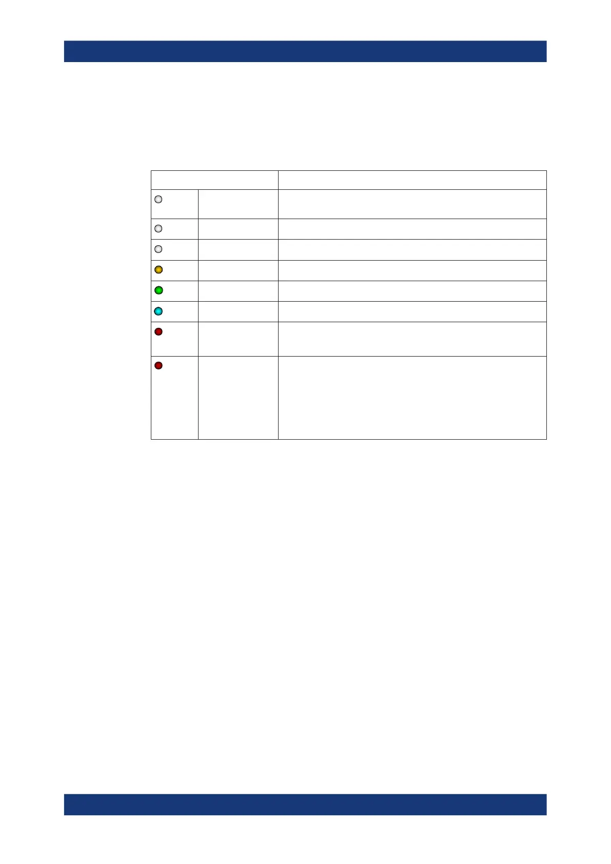
The status LED gives information about the state of the power sensor. The following
states are defined:
Indication State
White Idle state. The power sensor performs no measurement and is ready for
use.
Flashing white Firmware update is in progress
Slow flashing white Sanitizing in progress
Yellow Wait for trigger state
Green Measuring state
Turquoise blue Zeroing is in progress
Slow flashing red Static error
You can query the error type with SYSTem:SERRor?.
Fast flashing red Critical static error
You can query the error type with SYSTem:SERRor?.
Note: If this state occurs after a firmware update, the update was not
successful. Perform the firmware update again.
See also Chapter 11.3, "Problems during a firmware update",
on page 139.
4.3 Host interface
The host interface is used for establishing a connection between the power sensor and
a USB host. For this purpose, an external cable is needed. See Chapter 3.6, "Connect-
ing a cable to the host interface", on page 13.
4.4 Trigger I/O connector
The trigger I/O is a connector of SMB type.
It is used as an input for signals if the trigger source parameter is set to EXTernal2. It
is used as an output for trigger signals if the power sensor is operated in the trigger
sender mode.
Further information:
●
Chapter 8.5.2, "Triggering", on page 42
Trigger I/O connector

 Loading...
