b) Switching on the Transmitter
After you have inserted four new batteries, check the position of the toggle switches. All switches must be in the front
position.
Thecontrolstickfortheelevator/nodandaileron/rollfunction(seegure1,item7)mustbeinthemiddleposition.The
controlstickfortherudder/tailandthrottle/pitchfunctions(seegure1,item17)mustbeinthemiddlepositionaswell
or must be pushed into the bottom-most position (motor off).
Nowswitchonthetransmitterusingtheon/offswitch(seeg.1,item11).
First, you will hear three signal sounds in increasing pitch and the operating display with the currently set model
appears in the backlit display.
The backlighting is deactivated automatically about 20 seconds after activation or the last button operation. If no ope-
rating element ids operated within 60 s with the plant on, the plant will emit short signal sounds as warning note.
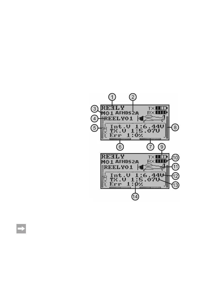
The operating display consists of the following elements:
1 Manufacturer logo
2 Digital encoding
3 Memory display
4 Model name display
5 Throttle/pitch trimming display (in Mode II)*
6 Rudder/tail trimming display (in Mode II)*
7 Aileron/roll trimming display (in Mode II)*
8 Elevator/nod trimming display (in Mode II)*
9 Battery symbol for transmitter voltage supply
10 Battery symbol for receiver voltage supply
11 Modeltypegure
12 Display of the receiver voltage
13 Display of the transmitter voltage
14 Display of the defectively transmitted transmitter data
* Further information for mode setting can be found in the system setting menu in the menu item „Sticks mode“.
Theoperatinginstructionsingure4appearcompletelyonlyifthereceiversystemisinoperation.Otherwi-
se, e.g. the values for receiver voltage or signal quality are not displayed.
Figure 4