* Electricmodels withanelectronic ightcontroller only requireaseparate rechargeablereceiver batteryifthe
ightcontrolleruseddoesnothaveaBECcircuit.Forfurtherinformation,refertothetechnicaldocumentsofthe
controller.
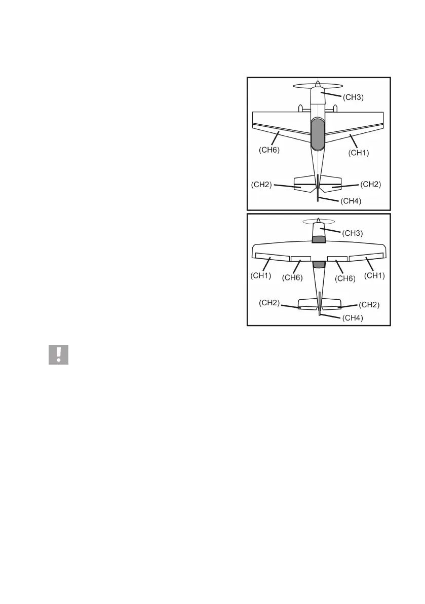
Channels 5 and 6 can be assigned differently depending on
model. There also is the option of operating two servos via a
V-cable at a receiver output.
For a possible setup or distribution of the control channel, see
theadjacentsketchesingure9.
If a model is equipped, e.g. with two aileron servos, the second
servo can be connected to a receiver output that has not been
assigned yet. The control is then performed via one of the three
freely programming mixers.
For more information on the servo connection and the mixing
functions, see the following chapters (programing of the remote
control transmitter) in the respective function.
Important!
It is recommended to use a pair of tweezers or long-nosed pliers to disconnect the connection. To prevent
cable breaks, you should always pull on the plastic casing of the plug to disconnect the connection. Never
pull on the cables.
b) LED Display
ThereceiverhasanLEDdisplaythatservesmainlyasanindicatorforthereceiverconditionononeside(seegure
8, item 2).
The LED is lit only when the transmitter is on and bound to the receiver in operation of the receiver. If the transmitter
doesnotrecogniseanyvalidtransmittersignal,theLEDashes.Moreinformationonthetransmitterbindingcanbe
taken from chapter: Binding Function.
Figure 9