RH850/F1Kx, RH850/F1K Series Hardware Design Guide
R01AN3841ED0110 Rev. 1.10 Page 103 of 108
August 8, 2019
8.4 Debug Considerations when Hot Plug-in is used
When it is planned to use the hot plug-in function for debugging the following topics should be considered.
RESET
pin
When the hot plug-in will be used it is recommended to consider the installation of a capacitor between the reset signal
and GND in order to suppress a noise. In this case, the time constant of the reset circuit shall be adjusted that the time
elapsing before the signal reaches 80% of the high level from the low level is within 900 µs.
Power source monitoring
When the hot plug-in function will be used it is recommended to configure the external circuit of the power source
monitoring at pin 8 (TVDD) of the E1/E2 emulator connector with a ferrite bead or inductor. This additional ferrite
bead or inductor is recommended to avoid a momentary drop in the power-supply voltage on the user system that could
lead to a reset of the microcontroller.
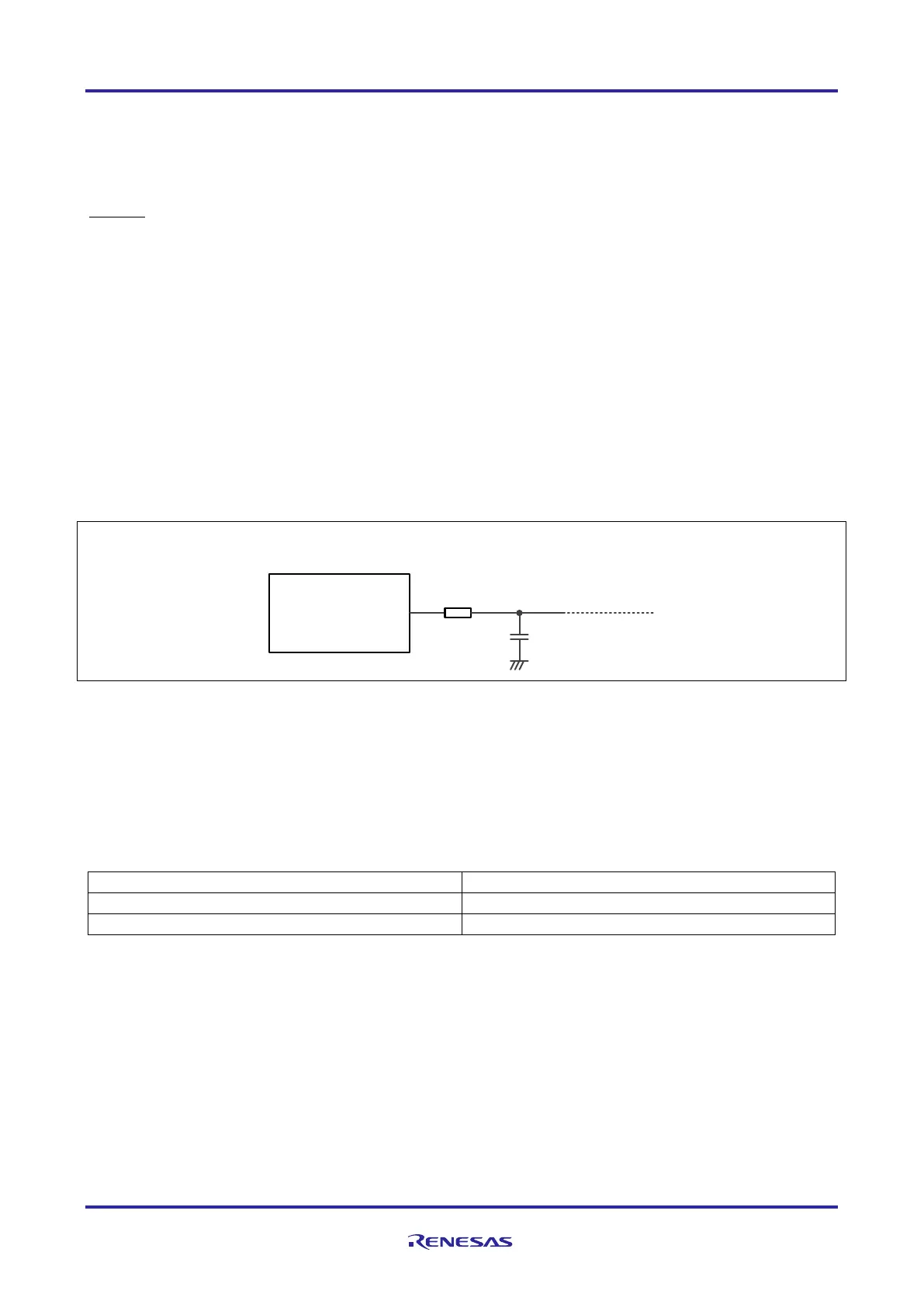
This effect can be reduced as shown in Figure 22 by placing a ferrite bead (or inductor) L1 and an additional capacitor
C1 near the TVDD line of the connector for the E1/E2 emulator.
Figure 44: Circuit configuration for hot plug-in
Note: This measure might not eliminate completely the voltage drop.
General guidance for the additional external components for the power source monitoring during hot plug-in:
Table 74: Basic component value for hot plug-in
The value of the capacitor C1 and the inductor/ferrite bead L1 depends on the application requirements.
TVDD
E1/E2 Emulator
(14pin Connector)
C1
8
L1

 Loading...


